Public places electrical safety
Low voltage electrical installation safety

After the installation passes visual inspection, electrical measurements are necessary to ensure operational safety.
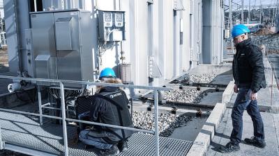
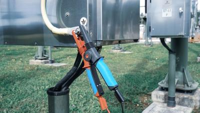
Earth resistance is measured at the main earth electrode. If there is space available and ground allows electrode placement, the 3-spike method is used. It involves driving two probes into the ground at a considerable distance (the further (C) at 5 times radius of the building complex and the closer (P) at 62% of this distance) from the electrode under test and using them to inject current and measure voltage. In urban areas, more often than not this isn’t possible. In many such sites, 2-clamp method should be used instead. It is also useful for testing lightning protection. It injects current into earthing system of the building, as close to the ground as possible. It calculates resistance of the whole installation – the more parallel earths are available, the closer the result is to resistance of a single rod. Both methods are described in more detail in their own notes.

Measurements
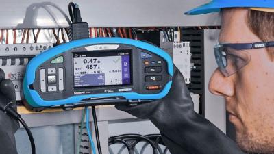
Continuity of PE wire and equipotential bonding - Continuity has to be tested with a 200 mA current and voltage between 4 and 24 V to conform to the standard. This measurement is usually done between the point under test and the nearest distribution board, and on the higher level between distribution boards and the point of supply, and eventually the substation to conform to the standard. Every contact and switch in the distribution board should be tested. The measurement method is chosen according to situation and grounding system to achieve the required accuracy. Accessible metal surfaces have the bonding checked periodically, while those concealed during construction are tested during initial inspection and when there is a fault.
In dry areas only the items that are large enough to be gripped or that can contact a significant part of the body surface are considered. Smaller items are less dangerous even if they become live. Touching them will cause the muscle to contract away from them breaking the contact.
It is important that within a single building there is no potential difference between any of the protective earths
For example it is possible to build a communication or computer system entirely separately, but it must still be connected to the protective earth system to ensure a common potential.
Insulation resistance and leakage current - Insulation prevents unwanted electrical contact and corrosion of the wire. Insulation resistance and leakage current are alternative ways to determine its quality. Insulation resistance is a test using high DC voltages, depending on the installation can be 250 V – 2.5 kV. This gives a pure resistive result with no capacitive effects outside the initial charge. On the other hand, leakage current is measured in AC conditions. It takes account of the capacitive elements of the insulation. The results are therefore not immediately comparable.
RCD testing - RCDs are automatic switches that turn the supply off if they sense a current in PE (or alternately a difference between currents in phase and neutral). This way, they provide protection from electric shock. There should be multiple, protecting different parts of the installation, and a hierarchy should exist between them. Some offer overcurrent protection as well, but mostly, overcurrent devices are separate. RCDs have to be tested for contact voltage, trip-out time, and trip-out current. Testing procedure consists of measuring trip-out time at different factors of the rated current. Contact voltage is the voltage between accessible grounded metal part and the PE contact on the RCD.
If the contact voltage is significant it usually means the PE is broken, this should also trip the RCD.
Line and loop impedances - Line and loop testing creates a short circuit between phases and measures the series impedance from the transformer leg to the measuring point. Line is the line-to-neutral impedance, and loop in the line-to-PE. The measurement is meant to test overcurrent devices and supply line impedance. Similarly, loop impedance tests overcurrent devices in the fault loop, residual current devices and PE impedance. In both measurement, the prospective fault current is calculated. It has to be high enough to operate overcurrent devices.
Electrical installation is not a simple system. The measurements can be an indication of its safety. Warning labels, symbols and inscriptions are part of the safety system as much as the electrical features, so the users are able to keep themselves safe. Once electrical safety of the installation is established, the wise manager will move to testing the appliances, and to functional testing.
Downloads
| Industrial catalogues | Language | Version | Release | Notes | Type | Size | Download |
|---|---|---|---|---|---|---|---|
| Building Facilities | en | 2023 | 18.12.2023 | 38.72 MB |

|