Public and workspace electrical safety in healthcare
Patient recovery rooms and hospital wards

Generally any inhabited space with electrical installation has to conform to safety standards. In Europe, they are written with protection of life as first priority. Public places have to conform to the standards and have a responsible authority confirm their safety before they are open to the public.
Recheck of the compliance is executed periodically during the lifetime of the building and installation. Following the safety standards means ensuring protection from electric shock, electrical fire and explosion.
Public places and workplaces are similar in their general intent: they are both filled with people who are not themselves responsible for the state of installations they use (except in the sense of avoiding damaging it). Workplaces usually contain some electrical appliances or machines that need special care, and the employees are instructed in their use. Safety of the installation is however established with the same set of measurements as for public space, as required by the standard families IEC 60364 and IEC 61439. Measuring equipment used is covered by IEC 61557. Measurements have to be performed by an authorized inspector. Commissioning and periodic tests are generally the same.
Commissioning contains some extra points in the visual test, before they are covered by décor, furniture or appliances.
Measurements include earth resistance, lightning protection, surge protection and equipotential bonding (see other notes in this catalog), insulation resistance, leakage currents, impedances in the lines and short-circuit currents, and RCD functionality.
The main way of determining safety, even with these electrical test available, is still visual inspection. Every accessible part of the installation has to be visually checked for adequacy and signs of degradation or corrosion. Great majority of problems is discovered visually. It includes everything from checking compliance to wire colours and warning inscription regulations to fire prevention measures.
Earth resistance
Earth resistance is measured at the main earth electrode. If there is space available and ground allows electrode placement, the 3-wire or spike method is the best. It involves planting two electrodes at a considerable distance (the further at 5 times radius of the building complex and the closer at 62% of this distance) from the measured point and using them to inject current and measure voltage. In urban areas, more often than not this is not possible. In many such sites, 2-clamp method can do the job. It is also useful for testing lightning protection. It injects current into earthing system of the building, as close to the ground as possible. It calculates the resistance of the whole earthing system as a large circuit of parallel rods, the larger the system, the more accurate the result for each earthing electrode. Both methods are described in more detail in their own notes.
Continuity of PE wire and equipotential continuity
Continuity has to be tested with a 200 mA current and voltage between 4 and 24 V. This measurement is usually done between the measured point and the closest switchboard, and on the higher level between switchboards and the supply point, and eventually the substation. Every contact and switch in the distribution board should be tested. Measurement method is chosen according to situation at hand and grounding system to achieve required accuracy. Accessible metal surfaces have the bonding checked periodically, while built-in construction is only tested before first use and in case of a fault.
Insulation resistance and leakage current
Insulation is a measure of preventing unwanted contact and preventing corrosion of the wire. Insulation resistance and leakage current are alternative ways to determine its quality between phases. Insulation resistance is a test with high DC voltage (depending on the installation can be 250 V–2.5 kV). This gives a pure resistive result with no capacitive effects outside the initial charge. On the other hand, leakage is measured in AC conditions. It has to consider some capacitance in the insulation. The results are therefore not immediately comparable.
RCD testing
RCDs are automatic switches that turn the supply off if they sense a current in the PE wire (or alternately a difference between currents in phase and neutral). This way, they provide protection from electric shock. There should be multiple RCDs, protecting different parts of the installation, and a hierarchy should exist between them. Some offer overcurrent protection as well, but mostly, overcurrent devices are separate. They have to be tested for contact voltage, trip-out time, and trip-out current. Testing procedure consists of measuring trip-out time at different factors of the rated voltage. Contact voltage is the voltage between accessible grounded metal part and the PE contact on the RCD. If the voltage is considerable, which usually means the PE wire is broken, the RCD should trip as well.
Line and loop impedances
Line and loop impedances include creating a short circuit between phases and measuring the series impedance from the transformer leg to the measuring point. Line is the line-to-neutral impedance, and loop in the line-to-PE. The measurement is meant to test overcurrent devices and supply line impedance. Similarly, loop impedance tests overcurrent devices in the fault loop, residual current devices and PE impedance. In both measurement, the prospective short-circuit current is calculated. It has to be high enough to operate overcurrent devices.
An electrical installation is not a simple system. The measurements mentioned above can indicate its safety, but it is important the users should have enough information be able to keep themselves safe. Warning labels, symbols and inscriptions are part of the safety as much as electrical features.


Measurements
Metrel offers an expansive line of installation testers. They are divided to single-function and multifunction. Single-function can perform one or at most two of the aforementioned measurements. Multifunction can perform all of them, and often extra.
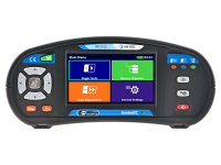
MI 3155 EurotestXD is the newest flagship of Metrel’s most advanced line of multi-functional measuring instruments. It is designed specifically for testing in industry, but useful for any kind of installation. It boasts an ergonomic design and an intuitive user interface, encompassing a memory organizer and fully programmable AUTO SEQUENCEs. It is controlled through a large colour touch screen. As is required for any instrument in safety testing, it is fully compliant to functionality standards for instruments (e.g. IEC/EN 61557) and the reference standards for the buildings (e.g. IEC/EN/HD 60364-4-41, ... )
The instrument can perform a wide range of electrical test and measurement, including TRMS current measurements, RCD tests, line and loop impedance tests with 3 and 4 wires, earth resistance measurements, on-line voltage monitoring, phase sequence testing, varistor testing, PI/DAR calculation, luminance measurement, discharge time testing, ISFL measurements, or IMD tests. Users are guided through both visual and functional inspections to reduce chance of missed faults, and graphic help screens are available for each measurement.
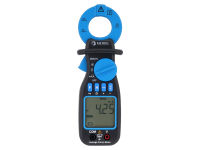
The full Metrel solution for public places in a hospital includes also instruments for regular testing of medical and other devices (MI 3360 M OmegaPAT XA) and general troubleshooting multimeter MD 9050.
Downloads
| Industrial catalogues | Language | Version | Release | Notes | Type | Size | Download |
|---|---|---|---|---|---|---|---|
| Medical Facilities | en | 2023 | 18.12.2023 | 34.02 MB |

|