Earth resistance measurement and 62% rule
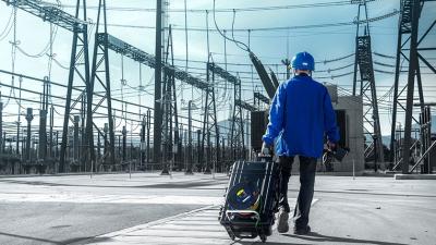
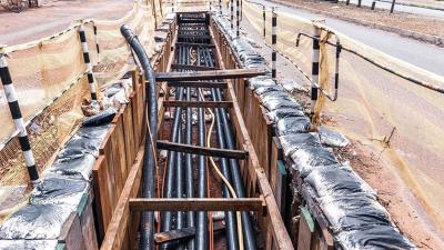
Power distribution
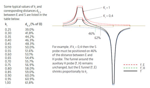
When performing the earth resistance measurement with the Fall of Potential (FoP) method you have to put the measurement S probe on a distance of 61,8% of the distance between the centre E of the tested earthing system and the auxiliary test probe H.
Application Notes
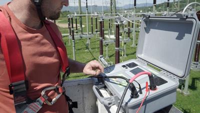


Measurements
The rule (recommendation) is defined in IEEE 81-2012 in Annex C. It is based on simplified model of rods and some additional preconditions:The rule (recommendation) is defined in IEEE 81-2012 in Annex C. It is based on simplified model of rods and some additional preconditions:- Current trough both rods (E and H) is the same: IE = IH - Uniform soil- Hemispherical electrodes If the distance between E and H rode is big enough, then the rods can be treated as hemispherical electrodes. If the soil can be treated as uniform soil then the following equations are valid:
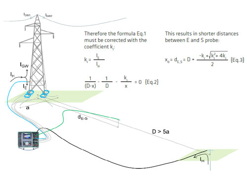
The distance between the E and S is calculated out of the following equation (C.9 in IEEE 81): 1/(D-x) - 1/D - 1/x = 1
The positive root of equation is the location of the S probe x0 = dE_S=0.618 D
The S probe must be located on the straight line between E and H probe.
During the measurement both probes E and H conduct a current therefore the potential around the electrodes raises (GPR – ground potential raise). The graphical presentation of this potential raise around the probe has a form of a funnel. In practice the distance between probes is finite (at least 5 time the diameter of the earthing system on the E side) and therefore the GPR of one probe is influenced by the GPR of the other probe. When performing the measurements of the potential raise around the probe only the summary of both GRP can be measured. Therefore simple measurement of the voltage between E probe and zero ground results in an error and one of the possible solution is to use the 62% method. Within this method and the above described preconditions the voltage between E and S (62%) is equal to the GPR of the E probe without the influence of the GPR around the H probe.
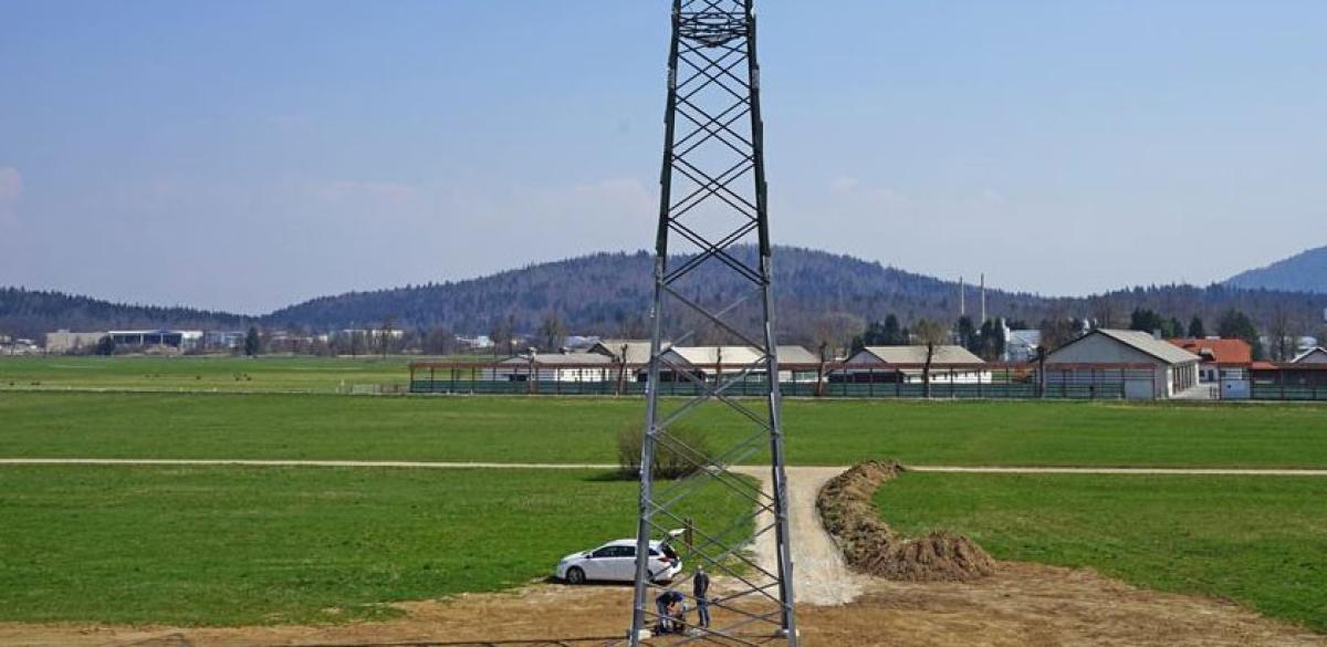
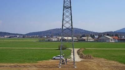
If earth resistance measurements on objects with auxiliary grounding are performed (for example transmission tower with overhead grounding wire) the condition IE = IH is not fulfilled. In such case the earthing current IE has to be measured separately with the method as described in IEEE 81-2012 Ch. 8.2.2.6 and implemented in MI 3290 Earth Analyser where measurements with multiple flex clamps are supported. In this case the generated test current is not the equal to IE.
Downloads
| Industrial catalogues | Language | Version | Release | Notes | Type | Size | Download |
|---|---|---|---|---|---|---|---|
| Electrical Energetics | en | 2023 | 18.12.2023 | 39.5 MB |

|