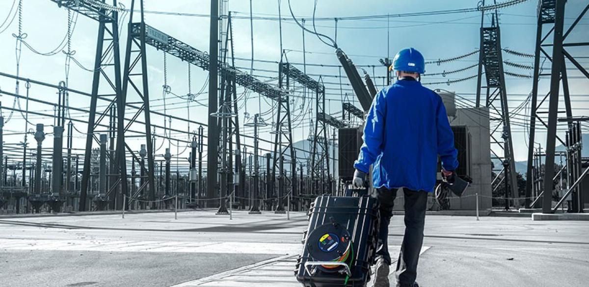
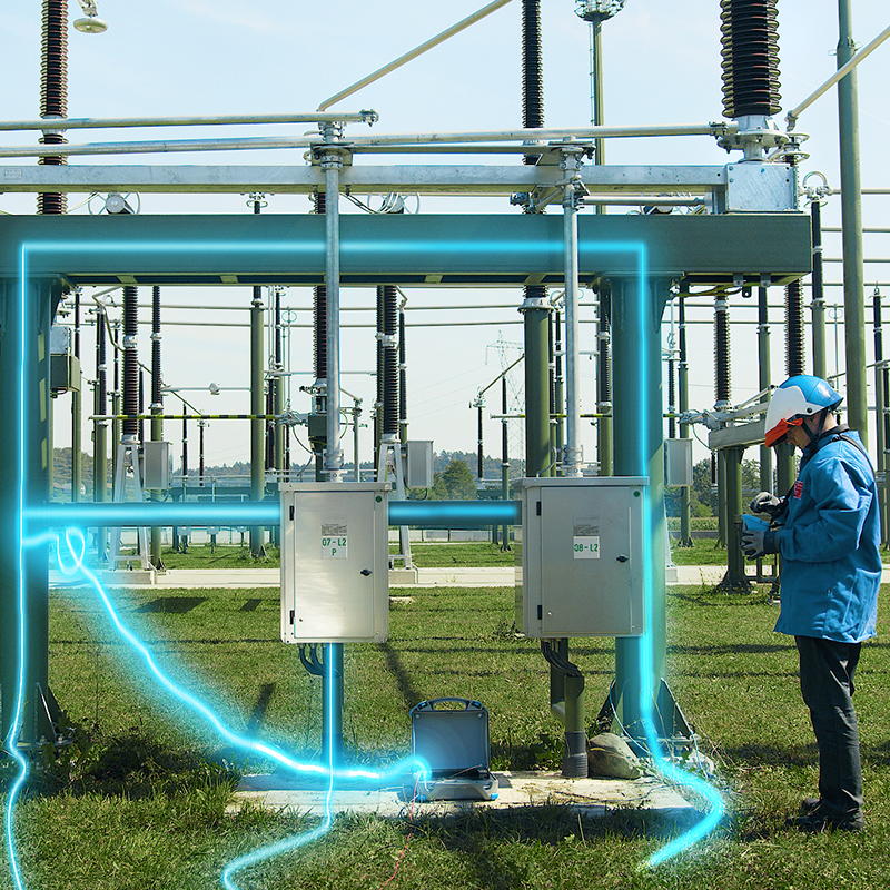
Ground integrity of conductive constructions with high current dR 300A
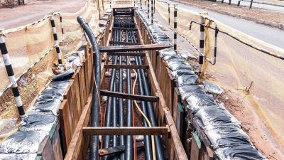
Power distribution
Voltage funnel is the function of voltage dropping with distance from the injection point. It is usually shown inverted so that the lowest point is at the injection point and it rises towards zero, therefore forming a funnel shape. With inversion, it is easy to add the funnels to schematic drawing of the location. When talking about a fault that induced the funnel, the phenomenon is also called earth potential rise or EPR.
The function is generally not analytically defined and is primarily used for illustration of different scenarios. Shape depends on many hard to quantify variables, like changes in resistivity in the ground, available moisture, temperature, and underground objects. Particularly conductive object can change its shape, which can be done purposely. The funnel can be quantified with measurements.
Size and shape of the funnel determines area of effect for the earthing electrode and therefore distances necessary between the electrodes for accurate grounding measurement.
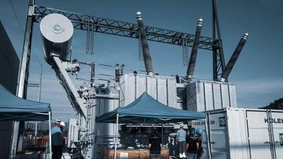
Application Notes
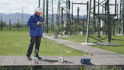
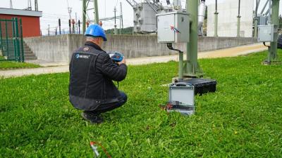
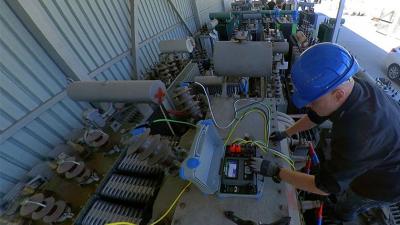
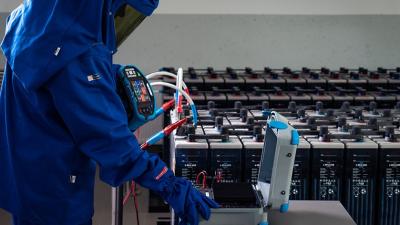
Measurements
Step and contact voltages are used to consider the funnel features. They can be theoretically calculated from the funnel function as difference in voltage values on the curve at the locations of feet or feet and hand. The function is steeper closer to the injection point, so difference between the points is bigger the closer to the source. Step and contact voltages are bigger close to the grounding electrodes or other injection points. This type of calculation should never be taken at face value, only measurements count.
Mesh voltage is potential difference between the grounding mesh and the place the person may be standing on. It is uncommon to be dangerous, but considering it must be part of the design process.
Integrity of an earthing system is continuity of every piece of bonding. It must cover enough area to make it safe. Equipotential bonding keeps the whole area at the same or nearly the same potential, which remains true in case of a fault or lightning. Low potential difference in the area means low voltage and low danger. However it also means that high potential caused by the fault will propagate to the edge of the bonded area before dissipating. Dangerous step voltage can happen there, sometimes quite far away from the original injection fault. The bonding must be designed to dissipate the voltage slowly over the area to lower step or contact voltage throughout the area. Design is helped with computer simulations.
Bonding integrity is hard to test. The system tends to be mesh shaped, so any broken wire will not show up when measuring continuity. The potential will however change with any hole in the system and create a chance of high voltage during a fault. Step, touch and mesh voltages can only be measured at a single point at a time. Schematics, plans and computer simulations or the location help choosing the points of measurement to test safety of the location.
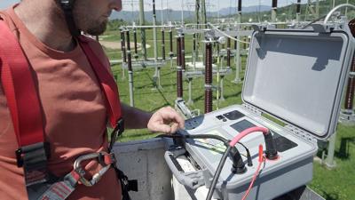
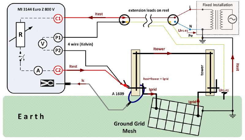
MI 3144 is the most powerful Metrel instrument that can (with the help of external power source) generate up to 300 A of test current. A current this high combined with smartly setup electrodes can reveal weaknesses in the mesh. It also supports measuring of step and touch voltages. Practical accessories like a choice of plate probes and weighed probes for step voltage ensure a good connection to the ground.
Downloads
| Industrial catalogues | Language | Version | Release | Notes | Type | Size | Download |
|---|---|---|---|---|---|---|---|
| Electrical Energetics | en | 2023 | 18.12.2023 | 39.5 MB |

|