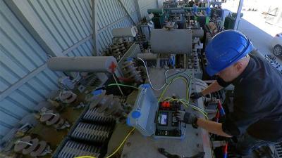
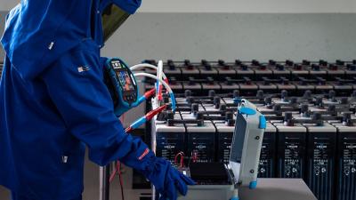
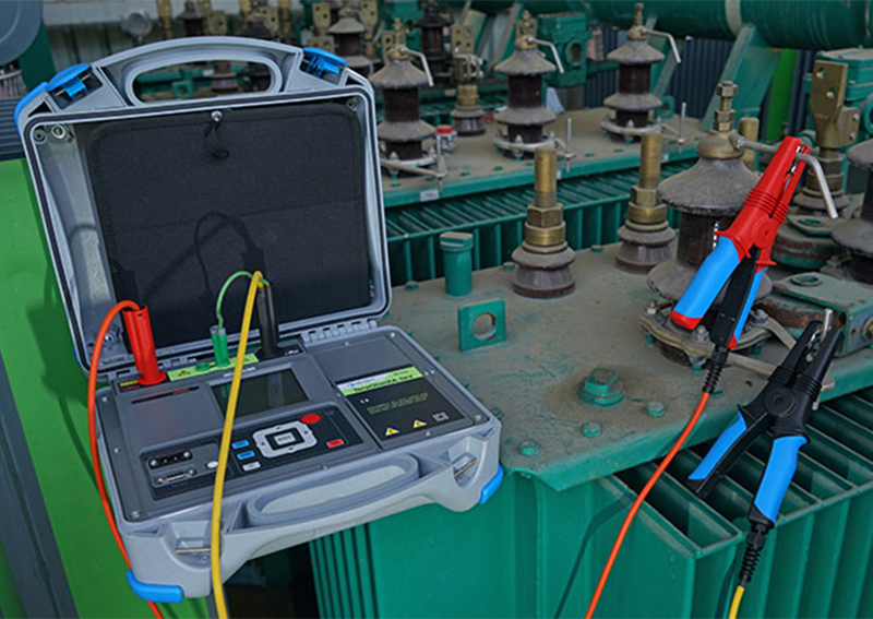
Insulation resistance measurement of transformer’s windings
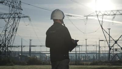
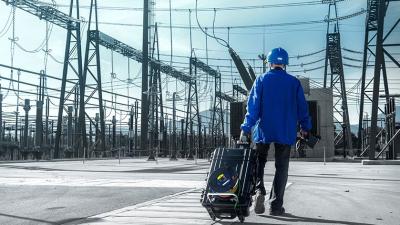
Power distribution
Insulation analysis, most commonly through insulation resistance measuring, is a staple method for assessing the state or “fitness” of an electric machine and its ability to operate within acceptable limits and identifying issues requiring maintenance or more comprehensive repair. All insulation materials used in modern electric machinery and installations are subject to high and fluctuating temperatures, chemical agents, atmospheric elements, mechanical forces and other factors that degrade their dielectric properties to a varying degree.
Resistance measurement is a simple, fast and relatively inexpensive method of assessing the extent of degradation and the need for repair. Though, some machines are more easily maintained and repaired than others, and sometimes it may be practically and economically more viable to allow continuing operation, albeit under modified conditions. Transformers are a prime example and insulation resistance measurements on primary and secondary windings can be a good guide.
Application Notes
Measurements
Extending the lifespan of a transformer
Most transformer failures, at least on medium-voltage (MV) and low-voltage (LV) distribution transformers, are associated with insulation resistance deterioration caused by improper operation (overloaded) or general (and predictable) ageing of insulation material. Regardless of exact cause (even though that may be important for one reason or the other), transformer operators are often interested in extending their lifespan as much as possible before replacing them with new ones.
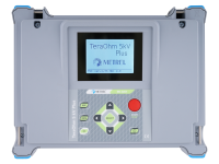
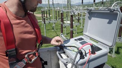
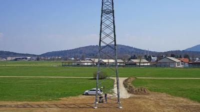
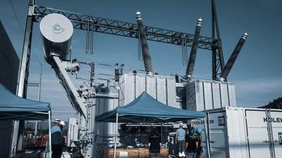
Let us take a look at a real-life example how this was achieved using the MI 3205 TeraOhmXA 5kV high-voltage insulation tester. A large electrical utility was in the process of modernizing a part of the distribution grid suffering frequent outages due to overloading by replacing older transformers with newer, higher-rated ones.
They were left with 37 20/0.4 kV 680 kVA (Dy5) transformers that despite their age were perfectly serviceable and could be used for the planned expanding of the grid to several, previously underserved areas. However, 15-25 years of operation, some of that in overloaded working conditions and when the thermometer showed 40 °C in the shade, took their toll on some of them, particularly the older ones. Quality assessment before restarting operation was therefore more than warranted.
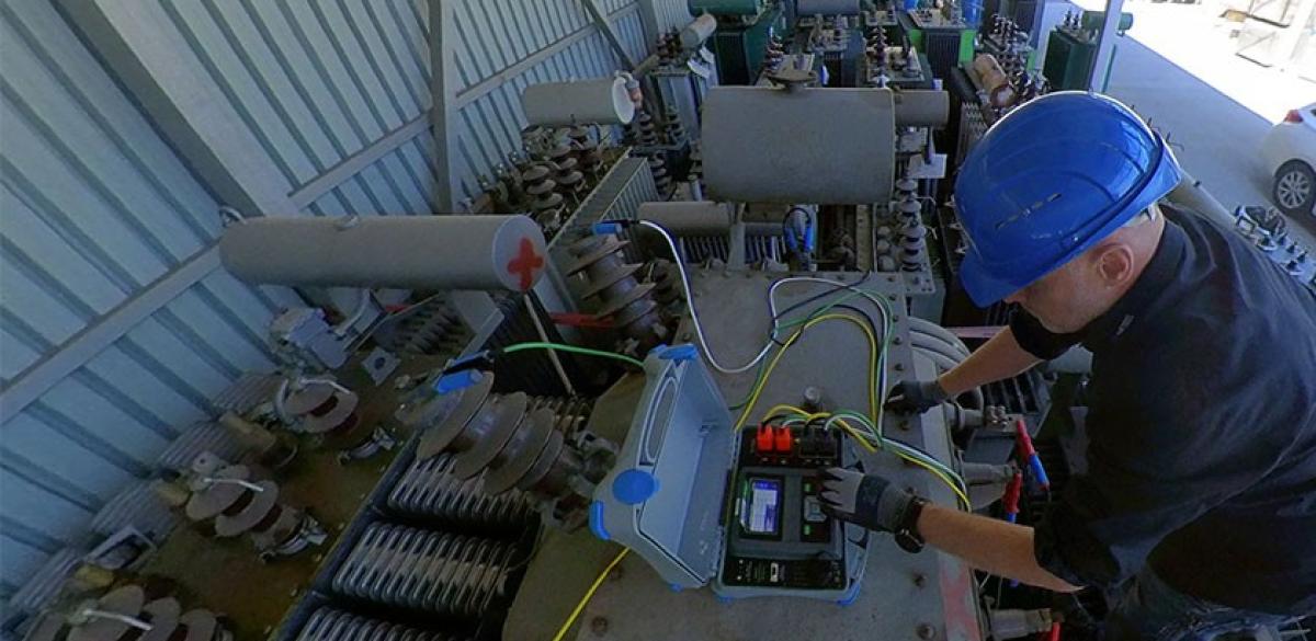
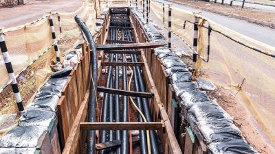
Insulation resistance measurement of primary and secondary windings was selected as the go-to method. There are of course other, more comprehensive and complex assessment methods and tools, but the chosen one was deemed sufficient for the purpose and could be done using the three MI 3205 TeraOhmXA 5kV they’ve already put to good use for checking cable insulation and were familiar with their operation.
Insulation resistance rule of thumb
Insulation resistance analysis (of windings) in transformers consists of 3 separate resistance measurements: resistance between primary and secondary winding, between secondary winding and main tank and between primary winding and main tank.
Generally, it is recommended that the insulation resistance is at least 1 MΩ for every kV of windings’ rating – at room temperature (20 °C). In our case that translates to 20 MΩ. However, recommended resistance steeply rises with rising working temperature. It more than doubles for every additional 10 °C. At 70 °C, the temperature chosen by the utility’s engineers tasked with transformers’ assessment as the highest they expect, this puts the windings’ insulation resistance at 635 MΩ.
This is without taking into account the safety factor, which was put at 30 %, giving the final number of 825,5 MΩ. Preliminary calculations done, the engineers set about measuring. There was seemingly just a small problem – the MI 3205 TeraOhmXA 5kV can output 5 kV while (primary) windings are rated at 20 kV.
Extrapolation to the rescue
Fortunately, this is not a problem for two reasons: (transformer winding) insulation material’s resistance at specific voltages is known (usually presented in graph form) and the MI 3205 TeraOhmXA 5kV supports step voltage testing (in 100 V steps for 1 to 5 kV measuring range). Engineers simply performed all 3 measurements, being careful to properly utilize the guard terminal on the tester, for each and every transformer and plotted the results for each measurement (from 1 kV to 5 kV), extrapolated them to 20 kV and compared them with material’s data sheet/graph. Measurements naturally took some time as capacitance of insulation was fairly large (the tester can manage 3s/μF) – discharge at the end was done automatically (another handy MI 3205 TeraOhmXA 5kV’s feature).
Valuable information
Surprisingly, 35 of 37 transformers passed the testing and were put in operation on the distribution grid. The remaining two were operational, but it was calculated they could safely operate only at a significantly reduced temperature and load and as such were unsuitable for the utility’s purpose – they were scrapped. Proof that a simple insulation analysis as done with the MI 3205 TeraOhmXA 5kV can be a valuable assessment method – for MV and LV transformers and other electric machines.
Downloads
| Industrial catalogues | Language | Version | Release | Notes | Type | Size | Download |
|---|---|---|---|---|---|---|---|
| Electrical Energetics | en | 2023 | 18.12.2023 | 39.5 MB |

|