Resistance measurement of dual-grounded high voltage circuit breakers
Power distribution
Switches and other types of circuit breakers have come a long way from simple copper knife switches that were used during first experiments with electricity and often put the operator at significant risk of electrocution. Nowadays, they have far superior designs and are made of higher quality materials – on top of standards and legislation that safeguard both users and manufacturers. However, they all still have a certain lifespan (under specific, prescribed conditions), some require special maintenance and may even be subject to periodic performance/safety testing.
High-voltage circuit breakers used at switchyards are an example of latter ones. We can’t really claim they are the most critical element since virtually all switchyard components are of critical importance and even just less-than-optimal performance of any of them can have catastrophic consequences. Breakers are, nevertheless, an important link in the whole chain of power transmission-to-distribution operation (and in other types of substations, not just distribution ones) and have to be regularly maintained and tested. The most basic type of assessment is resistance measurement, which can help identify breakers that have poor conductivity and are overheating. Though, safety measures used during the measurement may influence its accuracy, necessitating a special measuring protocol.
Application Notes


Measurements
Safety first
Testing and measuring in high-voltage environments comes with its own set of challenges and dangers, the main one being the danger of electrocution and fire (arc flash). Comprehensive safety protocols and appropriate safety equipment are a must, including (where applicable) double grounding that virtually completely isolates (already disconnected) the component from any power source.
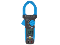
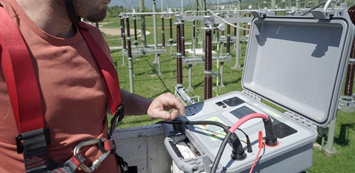
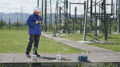
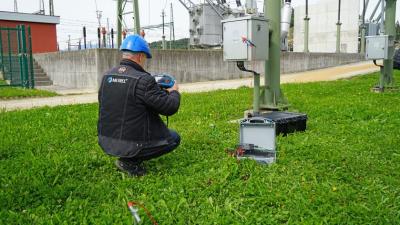
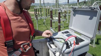
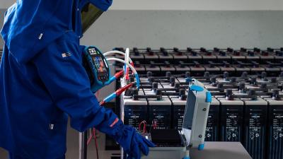
Said double grounding can also degrade the accuracy of certain measurements (e.g. resistance) and has to be compensated for. Fortunately, in spite of what is somewhat prevalent thinking that specialized equipment is needed in such cases, this is actually rather simple and can be done with an ordinary continuity tester and a current clamp meter with appropriate jaw size (grounding cables are usually large diameter). A MI 3252 MicroOhm 100A and MD 9231 Industrial TRMS AC/DC Current Clamp Meter – combo used by a group of maintenance engineers that were tasked with testing a group of newly installed and yet to be commissioned high-voltage circuit breakers at a large transmission substation (400 kV/110 kV).
The MI 3252 MicroOhm 100A is particularly suited for such installations, where extent and intensity of electromagnetic interference is significant and may radically influence the measuring accuracy. It can withstand electric fields in excess of 12 kV/m without any performance degradation – as found out by our group of engineers who reportedly also appreciated the portability of the tester, weighing a mere 11.8 kg.
4-wire resistance measurement
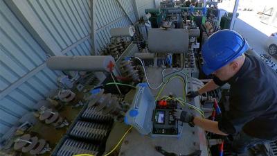
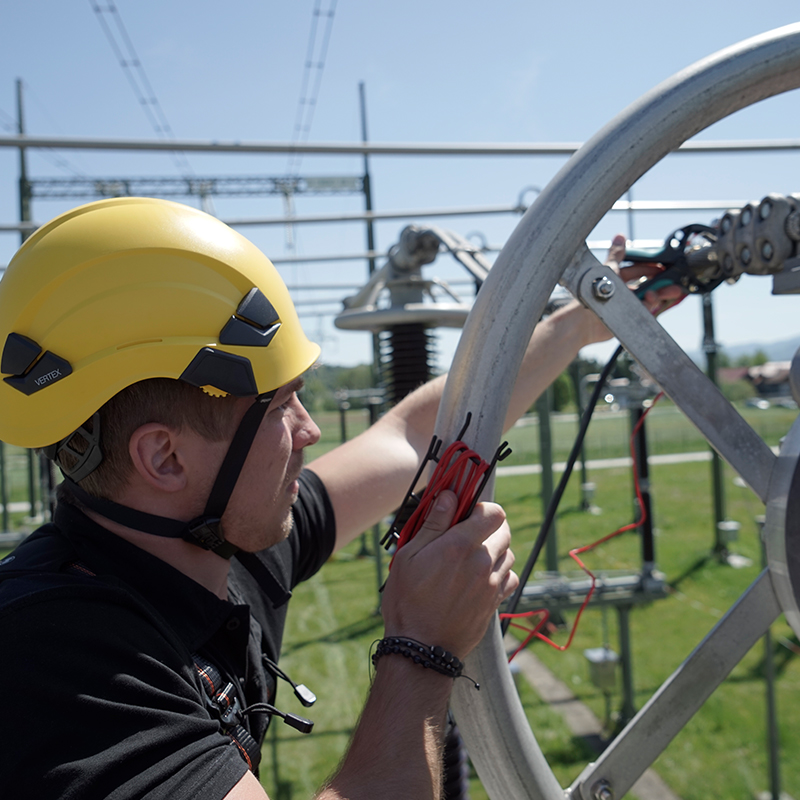
Six high-voltage breakers rated at 400 kV were tested. Each was dual-grounded for added safety of two engineers that were lifted to the top of the switch to measure resistance with the MI 3252 MicroOhm 100A using the 4-wire Kelvin method, which is a superior method for accurate measurement of very low resistances, particularly under field conditions.
The 4-wire Kelvin method, especially if combined with a high test current (the MI 3252 MicroOhm 100A can output 100 A), is inherently a very accurate method as it eliminates any error caused by test leads’ inherent resistance. However, the MI 3252 MicroOhm 100A also boasts proprietary noise-filtering algorithms that enable extreme accuracy with only 100 A (some erroneously claim that several times higher current is needed to achieve such or similar accuracy) – it can measure resistances as low as 1 nΩ with an accuracy of 0.25 %.
But, back to our breaker-testing engineers. They connected the tester to the switch, two test leads (with clips) on each side of the breaker and measured resistance. At the same time they used a current clamp meter, in this case the MD 9231 Industrial TRMS AC/DC Current Clamp Meter, to measure current through one of the grounding wires.
The humble yet essential current clamp meter
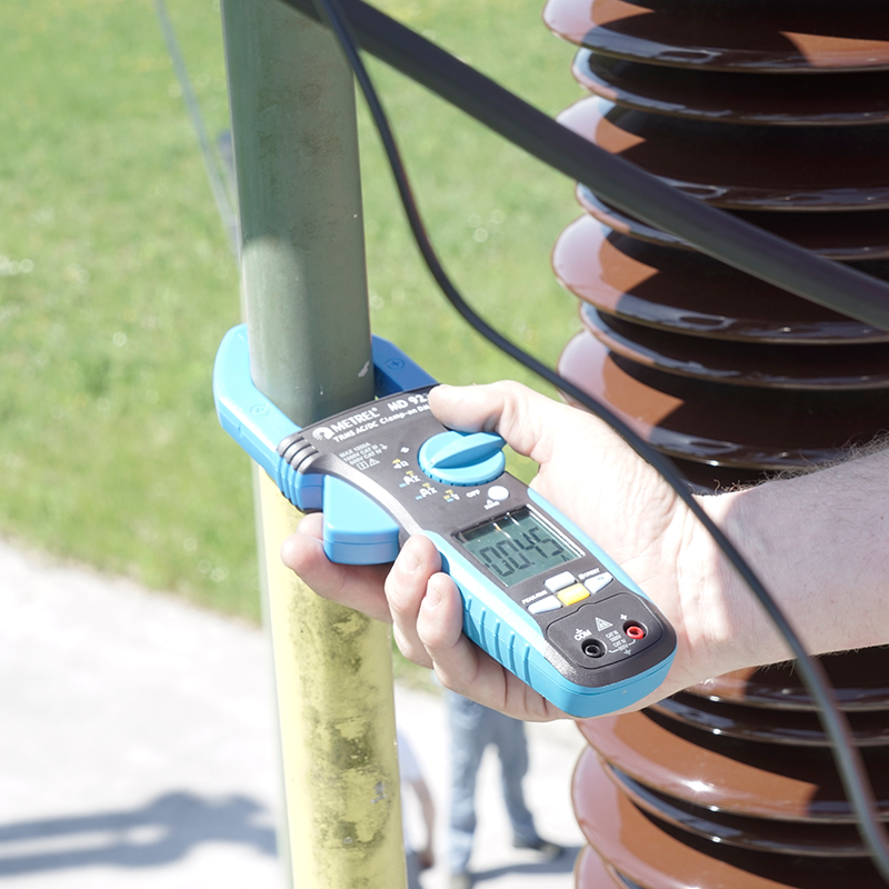
The two grounding connection, one on each side of the breaker complete a circuit, and it is inevitable that a fraction of the current the MI 3252 MicroOhm 100A injects in the switch will travel through the wire and ground. However, if the resistance of the breaker (contacts) is far lower than the grounding cables’, as it should be, only a small amount of current, measured with the current clamp meter like the MD 9231 Industrial TRMS AC/DC Current Clamp Meter, will flow through them.
Any measurement error (of resistance) will therefore be small and can be, if desired tolerances permit it, considered negligible. A higher current through the grounding cable, on the other hand, indicates an unacceptably high resistance of the breaker and can be simply calculated by subtracting the ground cable’s current from the injected current.
Calculations on the fly
In the case of aforementioned breakers the current through the grounding cables was indeed small and was measured with the clamps to be in the ballpark of 0.5 A for all of them. The relative error of resistance measurement (through the switch) was therefore around 0.5 % - acceptable by engineers’ standards who cleared all the tested breakers. The results were carefully saved for future reference - i.e. for periodic testing that can reveal material degradation (through rise in resistance) and the need for preventive maintenance.
Downloads
| Industrial catalogues | Language | Version | Release | Notes | Type | Size | Download |
|---|---|---|---|---|---|---|---|
| Electrical Energetics | en | 2023 | 18.12.2023 | 39.5 MB |

|