Single flex clamp method for testing building construction integrity for lightning protection
Power generation
Lightning protection systems and connected grounding systems are indispensable in protecting buildings and other outdoor-located objects, especially those associated with (electric) power generation and transmission, from lightning strikes and are therefore of special interest to electrical safety inspectors. Obviously, since any advantages offered by protective equipment (fuses, RCDs etc.) inside objects are usually rendered useless if there is no first-line defence against extreme, but short-lived electromagnetic phenomena (lightning and its many effects).
It should therefore come as no surprise that the lightning protection on buildings with Faraday cages and metal shields connected to conductive construction of the building must be tested periodically to check the connections from the lightning rods to the grounding nets.
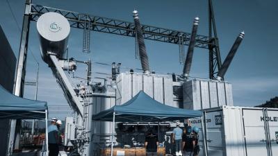
Analysis of lightning protection systems is in other words of paramount importance and encompasses assessment of protection levels both outside and inside buildings. The latter is usually done through equipotential bonding and installation of type 1 and type 2 surge protection devices (SPDs). Analysis of a lightning system also includes careful examination of building’s surroundings, up to 20 m away from the building. Like it was done for a large lightning system of an 870 MW coal-fired power station with a combination of the MI 3144 Euro Z 800 V and MI 3155 EurotestXD testing devices.
Application Notes


Measurements
High current needed
An older (30 year) coal-fired power station was given a comprehensive overhaul, which also included a complete refitting of its lightning protection system. As is usual or should we say (legally) prescribed, it had to be, like the power production machinery and virtually all other systems, thoroughly tested before the plant was (re)commissioned and started producing power. There are several established methods for analysis of lightning systems, but the high current one is the most relevant and most often requested.
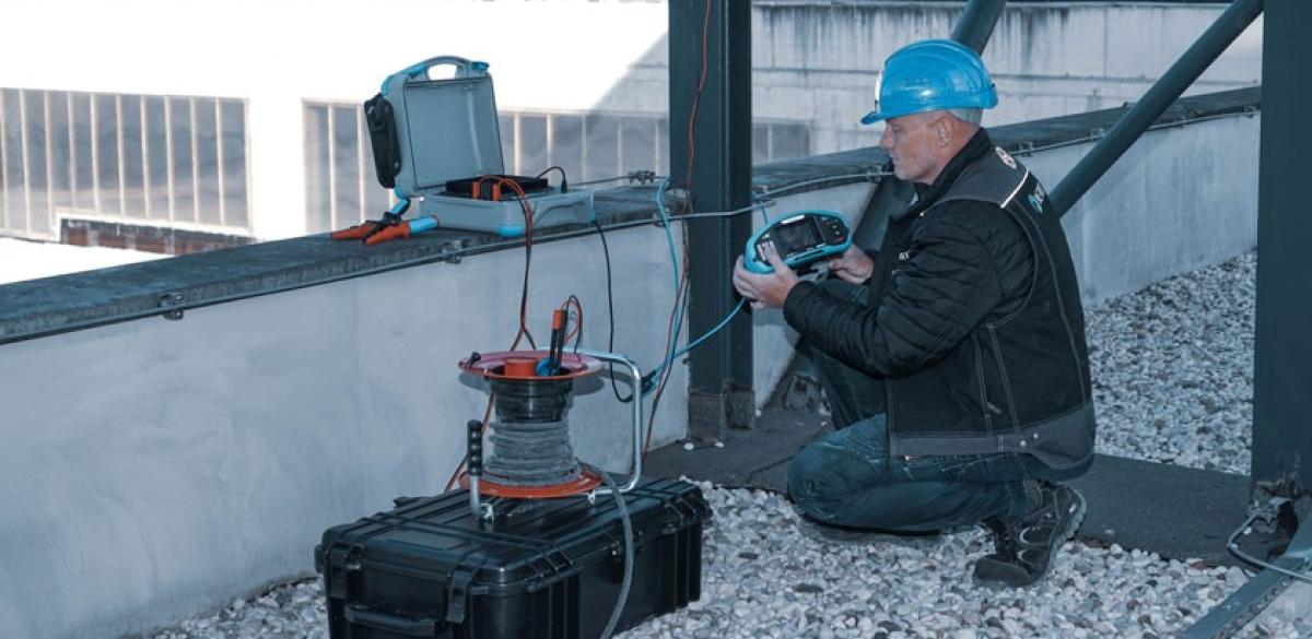
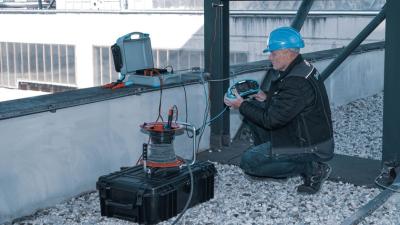
The high-current test method encompasses the use of an AC high-current source (pulses up to 300 A, but limited to less than 10 milliseconds in duration for safety reasons), which is connected to the lightning system, in this instance at the highest point (roof) of the lightning system or very nearly to it, and a voltage/current measuring device. The latter was in this case the MI 3144 Euro Z 800 V with MI 3155 EurotestXD (acts as a remote control unit). Both devices are fully portable and were easily transported to the roof by an electrical safety inspector that was tasked with testing the lightning system. High current dR 300A testing with MI 3144 Euro Z provides enough power while still being small and portable enough to be easily brought to any roof or part of industrial platform.
Flexible reach
Once on the roof, the inspector connected the MI 3144 Euro Z 800 V to one of the large lightning rods using both a G-clamp (for 300 A current injection) and an A 1609 1-phase flexible current clamp. Other types of current clamps may be used, but flexible current clamps (Rogowski coil) are particularly well suited for this type of work as they can be used on hard-to-reach or larger objects like large cross-section conductive parts of building’s construction. Such external flex clamps can be wrapped around any metal leg or construction with high cross-section, enabling easy evaluation of partial currents.
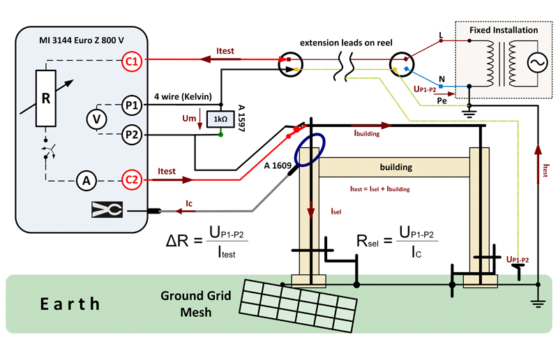
High Current testing with controlled power management of the source pulsing current. Safety mannered procedure where partial current Ic measured in synchronization with voltage drop U P1-P2 gives result of separate earthing leg resistance.
Another vital piece of equipment that the inspector had with him and that we nearly forgot to mention was A 1660 Extension test leads on reel, 75 m, red, green, 2.5 mm2. Buildings such as power plants are large and standard test leads are too short to reach the ground where a voltage probe (for voltage drop calculation) has to be placed. This was the job of the assistant inspector who had to make sure it was sufficiently distanced from the main building and near a selected main earth terminal.
Synchronization is key
For the lightning system to do its job, all the interconnected elements, from the rods and conductive strips and any equipotential bonding points, should have very low resistance all the way down to the reference ground. Therefore, it is desirable that the injected current used in the (resistance / impedance) measurement is split through the entire system evenly.
This is practically, sans in very simple lightning installations, virtually impossible to achieve, necessitating several measurements to get a more comprehensive picture of the tested installation. In other words, we are talking about measuring partial currents in sync with the voltage drop as measured with the help of a probe at the distant terminal.
Rsel = UP2 - UP1 / Isel = RA
With the MI 3144 Euro Z 800 V this is easy as everything is automatic and the user, in this case our intrepid inspector on top of the power plant, merely has to press a button (after carefully checking everything is properly connected) and wait for the result to appear on the screen of MI 3155 EurotestXD. It can then be saved on the tester itself and sent (over the Internet) to a PC via software or an Android app for more in-depth analysis. Like it was done by our inspection team that deemed the lightning system’s performance excellent, paving the way for quick (after other performance reports were collated) recommissioning of the power plant.
Downloads
| Industrial catalogues | Language | Version | Release | Notes | Type | Size | Download |
|---|---|---|---|---|---|---|---|
| Electrical Energetics | en | 2023 | 18.12.2023 | 39.5 MB |

|