Using disconnected transmission lines in ground resistance measurements
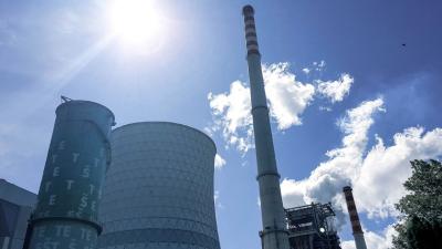
Power generation
Measuring a large earthing system is difficult. It takes extremely long wires, possibly multiple kilometres long, and repetition of the measurement at different locations to validate the result. Some of these problems can be eased by using the existing transmission lines as measurement wires, but this idea comes with several issues of its own. In theory, the method is quite elegant.
Particularly large complexes like power stations need to have the earthing measured at a great distance, however, there are wires already available in the form of transmission lines. Being a power station also eases the bureaucracy necessary for disconnection of a section needed for measurement.
Application Notes
Measurements
At both ends of the section, the line wires are connected together and grounded. On the measurement side, the instrument is connected between the line and the ground. A powerful surge protection is installed parallel to the instrument. Only then can the grounding wire be removed. A loop is created between the line wires and returning underground, and the grounding resistance can be calculated by the instrument.

Schematic of using the disconnected lines for measurement. The potential parallel lines that could cause dangerous inducted currents are not pictured.
An important advantage of this method is easy estimation of the current in the loop. The resistances in the loop are the wires, the earth resistance at the far point and the measured earth resistance. They are all generally low, so the method can make the most of the instrument’s power.
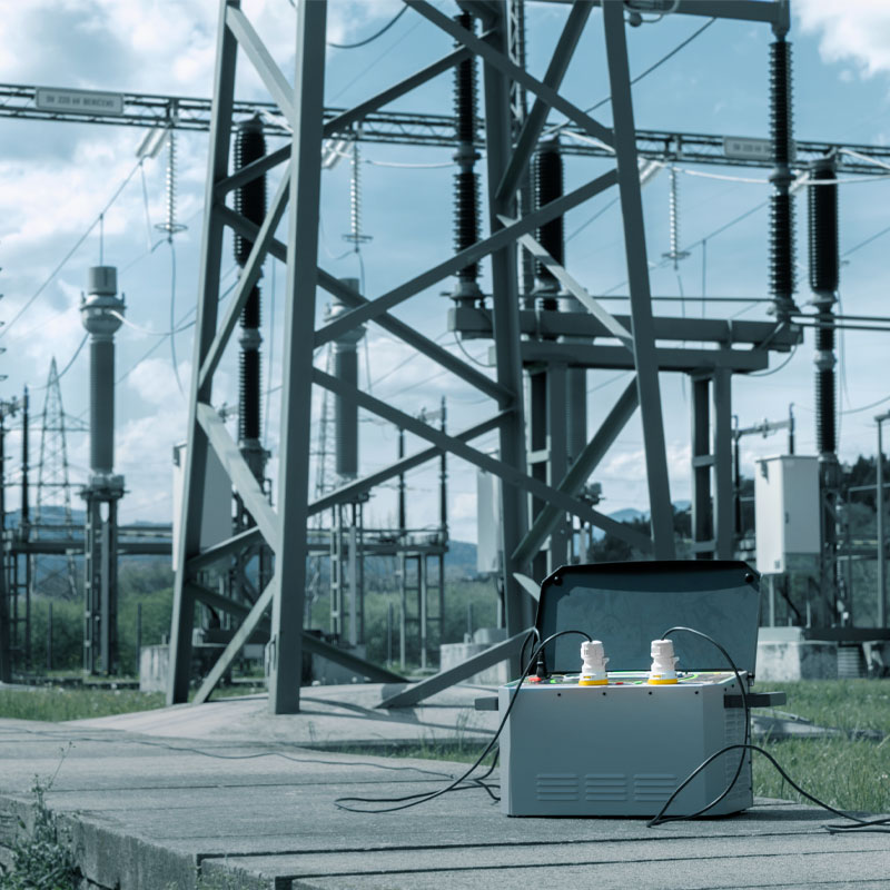
The Metrel solution for this method is the Step Contact Voltage Measurement system MI 3295 of base station and autonomous meter. The measuring system MI 3295 station provides 350W of power for earth measurement, which gives an estimated current up to 55 A max where safety voltage level is used 55 V max at frequency of 55 Hz to filter all the noise from measured signal in mV range. No additional recalculation needed to eliminate the presence of 50 Hz signal from the result.
Compared to classic methods with remote transformers on 50 Hz the robustness of the result is enormous better and much more reliable. Even the high generated currents above 50A could mislead the operators and give the completely wrong results in situation where the voltmeters are not synchronised to the source or where the vector diagrams are wrongly interpreted.
The 55 Hz method with synchronized voltmeter and generator, sensitive range and robust modern algorithms and filters nowadays can provide better results on 10 times lower the generated current. And the effectiveness is very easy to prove. Simply turn off the generator and the result on voltmeter will measure 0.00 mV range whereas the best TRMS voltmeters can vary the results in several volts.
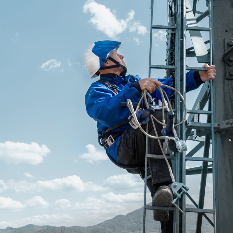
Another great advantage of using the generator on 55V is the level of safety. There is no need to clear the area during testing like with 400 V systems. Any surrounding of electrical energetic installations, power generation systems, substation or industry stays safe during measurements that could lasts for days when analysing voltage funnels, step voltages, contact and touch voltages.
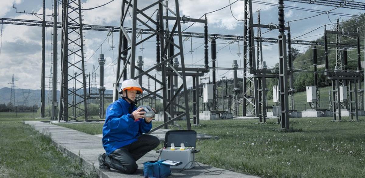
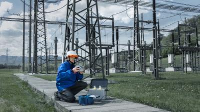
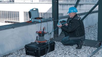
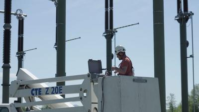
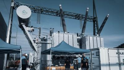
See the images below from a thermal power plant through 400 kV substation for your reference.
1. Connect the generator between grounding RE and disconnected transmission lines.
Power and resistances are easier to find or estimate than the voltage in this loop would be. Connect the E and ES cables to the electrode under test. Connect the surge protection in parallel to the instrument, between the measuring cables and the ground. Only when protection is installed, the grounding on the line wires can be open. S and H contacts are connected to the line wires. This is an extremely important safety precaution. Only then, connect the measuring contacts S and H to the line wires.
I= √2 350 W / RH+ Rl1 || Rl2 || Rl3 + RE
2. Ground the line wires of an disconnected transmission line at a pylon on appropriate distance at least 2.5 times (better 5 times if possible) the diagonal of the substation platform.
3. Use the pylons at 62% and others in surrounding to measure the funnel spreaded.
4 .Get several results from different locations to find the funnel S curve where the result is approaching to the real value.
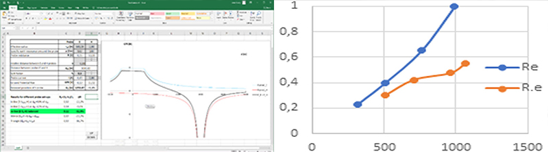
a. RE blue line is the example when the distance to the grounded pylon is too close to the substation, the result can not be found – example for our 500 m of diagonal of substation with grounded pylon 1 km away.
b. RE red line is the S curve where the result can be found in the middle of S curve – example for our 700m diagonal of substation with grounded pylon 2 km away.
Downloads
| Industrial catalogues | Language | Version | Release | Notes | Type | Size | Download |
|---|---|---|---|---|---|---|---|
| Electrical Energetics | en | 2023 | 18.12.2023 | 39.5 MB |

|