Two clamps method for measuring earth loops in a solar plant
Renewable energy sources

Measurement of earthing with two clamps has a number of advantages. It is useful for distributed earthing system with a lot of electrodes or for lightning systems that form earth loops which also cannot have their connection to earth severed. Where these two features are present, which is common, the 2-clamps method is the only appropriate standardised testing method.
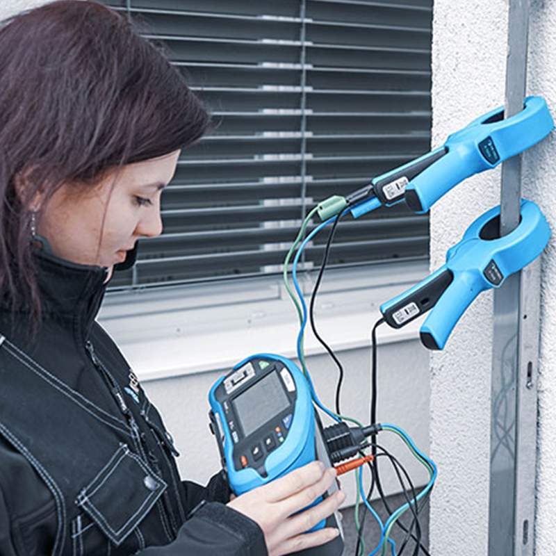
It is possible to perform in most environments: urban or rural. It only requires current clamps, an instrument with a generator for injecting the current, and the stretch of wire between the earth and the first crossing with other bonds. No bond needs to be disconnected.
Current is injected into the conductive construction. Where the loops are finished through the grounding material or earthing leg, the current clamps shall inject and measure the earthing leg as close to the electrode as possible. A voltage-inducing clamp is used, which can generate several amperes of current using the high transformer ratio of 1000:1 or similar. The measurement taken is a loop measurement: the induced current flows through all the connections of the earthing system and the earth. Loop current and voltage drop in the loop are sensed using the same pair of clamps. If a loop is not closed, no current cannot flow and the measurement is not possible. In isolated solar systems, it is strongly advisable to create a network of lightning rods and parallel loops at appropriate safety distance from each other. Use parallel earth electrodes to lower the resistance to earth and any voltages between points. Robust equipotential bonding is also an integral part of a safe system.


Measurements
A solar plant has a number of connections to the ground that generally do form interconnected loops with one leg through the ground. There are nearly no locations where the last stretch before ground is not accessible. These features make it a good candidate for the 2-clamp method.
The more parallel earthing rods there are in the system, the closer the resistance of the single rod will be to the measured value (for example with equal resistances of 10 Ω in Equation 1). It is a quite straightforward consequence of essentially measuring a leg of series-parallel circuit made up of the equipotential and ground network in a facility. If the measured electrode has high resistance, that will be immediately obvious. However, the measured result is earth resistance of the whole system. If one of the electrodes in the system is defective, or if there is another small fault in the loop, the change in value might be negligible. It pays to record the trend of previous measurements and look for the problem if measurements start increasing. This is particularly essential when testing lightning protection. The extremely high energy of the lightning strike can damage the vicinity of the weakened electrode much more severely.
The 2-clamp method includes no way of proofing the result similar to changing the positioning of electrodes in the 3-wire method. The results have to be taken in good faith, which is why a good understanding and careful execution of the method is critical.
There are two specific cases where the method will not work. First is if there is no loop to measure, and the second is if there is another low-impedance path to earth aside from the ground (for example an antenna). Another consideration is the possibility of connection between the earthing electrodes underground. The injected current will then travel by this connection instead of into the ground, and the result will be falsely low. It is very important to consider the documentation on design of the lightning or grounding system to find any underground interconnections between loops that may be accessible through covered earth shafts.
Solar plant, if designed well, should conform to requirements for the two-clamp method for lightning protection systems. Careful testing of equipotential bonding is crucial for its continued safety.
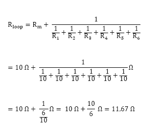
Equation 1: Example of calculation for 6 earthing electrodes with 10Ω resistance each. Rm is the measured leg.
A pair of clamps is also a part of the EU standard set of the multifunction tester MI 3155. The difference between the clamps is the connectors: A 1018 has integrated test wire for connection to the red and black current clamp sockets on the instrument connection panel, and A 1019 has connectors for standard 3-wire test leads, which is inserted into the test connection of the instrument and the blue and brown 4 mm plugs. The green 4 mm plug is attached to the socket at the back of the brown plug. The only variable parameter is maximum acceptable resistance for pass/fail indication. The measurement is entirely automatic, and it is unimportant which clamp is above or below. Press the test button to make a measurement and save the result for the documentation. All the above earth loops shall have very low resistances. An older regulation recommended results below 1 Ohm but newer standards recommend results below 0.2 Ohms, or in some cases below 0.1 Ohm. For example, protection of potentially explosive locations like solar plant on gas station would need to have grounding resistance below 0.1 Ohm.
Other Metrel instruments that can perform the 2-clamp method include MI 3290 Eearth Analyser, MI 3123 SMARTEC Earth/Clamp, installation testers MI 3152 Eurotest XC and MI 3102 Eurotest XE.
Downloads
| Industrial catalogues | Language | Version | Release | Notes | Type | Size | Download |
|---|---|---|---|---|---|---|---|
| Electrical Energetics | en | 2023 | 18.12.2023 | 39.5 MB |

|