IT system
Special locations
Any installation that needs 100% power availability must be constructed with the neutral isolated from the local transformer’s ground or earth. Such systems are critical parts of hospitals, communications transceivers, airports, and other. This type of construction has a number of advantages in terms of power quality and availability. First fault only generates an alarm, but the system remains functional and safe. The fault current is very low, the nominal voltage rises a little and leakage on the equipment rises very slightly. To conform to the standard IEC 61557-8, voltage between accessible surfaces cannot exceed 50 V. Construction of an IT grounded installation is generally more expensive than TT or TN, and the maintenance can become complex in the long run, particularly if it is large. Therefore, it is usually constructed as an island or islands in a TT or TN grounded building.
Isolating transformers - An isolating transformer is a transformer whose primary intent is galvanic separation of parts of installation or device. It works as an input to an IT island in the TN/TT installation. It is usually a transformer with a 1:1 ratio, with the galvanic separation between primary and secondary – not an autotransformer. It must conform to the standard IEC 60364-8 that requires a range of power 0.5 kVA to 10 kVA and maximum line-to-line voltage 250 V.
Isolation monitoring device - Monitoring device is installed between phase and protective earth. As the insulation degrades, the resistance between phase and PE reduces and a current starts flowing to ground. The IMD senses a voltage drop on the measuring resistance and alarms once the leakage current is significant. Exact measuring principle used depends on the system to be measured and can be proprietary. IMDs mostly include some form of interference suppression. Its own leakage or use of high voltages in the vicinity might otherwise influence the results. It must be able to measure both symmetrical and asymmetrical insulation faults, as required by the standard IEC 61557-8. Symmetrical fault is one where insulation on all connected conductors fails in the same way. Asymmetrical is the degradation the insulation of a single wire, or connection to a faulty device. IMDs are mainly meant as an early warning and a call to maintenance. They can have a built-in self-test, or they can be tested by changing the resistance between phases with an instrument. Limit for bad insulation is most commonly 55 kOhm.
RCD protection - RCDs should not be activated at the first fault in an IT system. The leakage at first fault is barely measurable, so there is no reason for RCD to trip. It can sometimes happen due to combining higher leakage currents from large appliances. That should be taken into the account when designing and maintaining protection. At first fault, IT system should essentially start working as TN/TT system, and as such needs to be protected with RCDs. Second fault current can be exceedingly high, creating a fire hazard and severe danger to life.
Fault finding system - Locating the fault in an IT system is its main limitation. There is only one IMD (as opposed to a number of RCDs in other earthing systems), which can make looking for a fault a major operation. Fault locators are devices that help with that. They are systems of current transformers at different points in the installation. To find a fault, a brief simulation of a ground fault is induced with electronically controlled current magnitude. A circuit is formed from the live conductors via insulation fault through PE and back to the tester. CTs measure the current in any relevant point in the network. Fault can be located by comparing the measured values to expected ones, or by observing the current dividing between the branches. The system has to be built in along with the IMD, and is usually very expensive.

Measurements
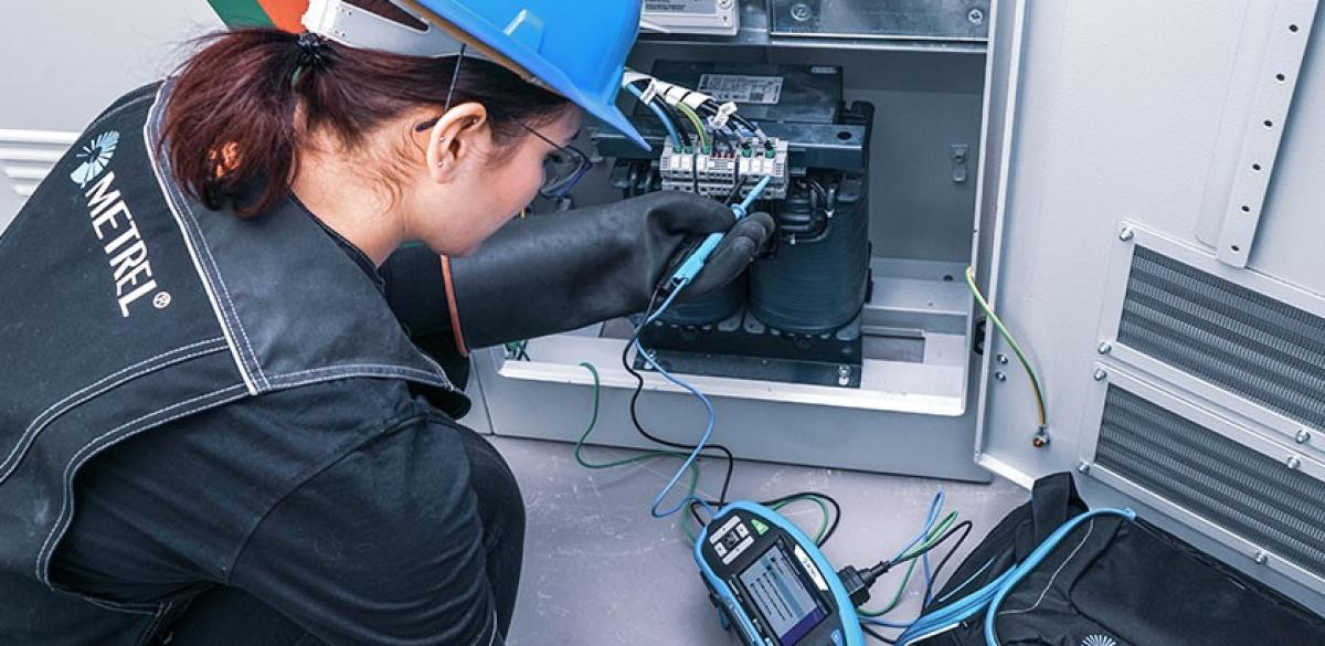
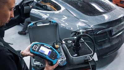
There is a choice of multifunctional testers with support for measurements in IT grounding system in Metrel’s portfolio, and one specialized tester that requires no electrical knowledge. They all work with the concept of Autosequence®s. There is nothing that can go wrong using them for testing. Tests collected into the Autosequence are insulation monitoring device test, mains voltage and frequency, first fault current measurement, voltage drop and line impedance test. Troubleshooting can be done with MI 3155 2-clamp method. It generates a signal into the network while the second clamp can be used to search for it. If there is an obvious drop in it, there must be an insulation break somewhere between source and measuring point. MI 9273 as an adapter can work this method wirelessly with its 128 Hz function.
Downloads
| Industrial catalogues | Language | Version | Release | Notes | Type | Size | Download |
|---|---|---|---|---|---|---|---|
| Building Facilities | en | 2023 | 18.12.2023 | 38.72 MB |

|
Videos


Instructional

Instructional

Instructional

Corporate
#Metrel #corporate #video
An updated Metrel corporate video.
—