Earthing measurement with fall of potential method
Low voltage earthing and lightning protection
Measuring earthing resistance can be both difficult and tedious. It requires special equipment and multiple repetition of measurements, particularly on large systems with multiple earthing points.
The fall of potential method, also called the 3-wire or 3-spike method, is a common way of measurement and the first recommendation by standard IEEE 80. It is particularly useful for earths in remote locations. The three measurement spikes are the earth electrode under test and two extra, often labelled P (for potential) and C (for current). Metrel instruments however use notation S for potential and H for current. The measurement principle is very simple. The H electrode injects current into the system that comes out via the electrode under test, and potential difference between S spike and the electrode under test (denoted E) is taken. Resistance is calculated using Ohm’s law. The PE (or PEN) of a TN system should be disconnected. If a single earth electrode is to be measured, it should be disconnected from the rest of the system.
However, we have described the idealised case. Every electrode has an area (or effective radius) of distributed resistance in the earth. To achieve accurate measurement, the electrodes must be far enough from each other that the areas of effective resistance do not overlap. If the electrode S is too close to E, the result will be too low, as only part of the measurement funnel will interact. If the electrodes S and H are too close together, the H electrode funnel will impact the result.
Other important source of inaccuracy is presence of conductive materials underground like pipes or fences.
The distances depend on the size of the longest diagonal or diameter of the protected object. Distance, D, between E and H should be at least 5 times its greatest dimension. The electrode S is placed at 62% of distance, D, from E. There are some variants of this method with different electrode positioning. If there is particularly large space available, the 5 times distance can be extended and the S electrode put at halfway. This allows measurement without a measuring tape.
The electrodes can also be placed as vertices of the equidistant triangle. Measurement result at any electrode positioning should be checked by repetition at different distances. S electrode is moved about 10% closer to, then further from the E in regard to original position. Standard IEC 60364 -6 advises moving it by 6m each time. The reading shouldn’t change more than 10%. Otherwise, the probes should be moved further away from the measured electrode. If there are suspect object underground, perhaps moving them to a different position would help.
It is good practice to repeat the measurement with different electrode positioning. At least they should be put to the other side of the object under test, at 180 degrees from the first measurement.
Distances can be impractically large even for medium-sized objects. The method can rarely be used in urban areas, where access to earth is also a problem. It however works well in remote areas, and it is the only method that can be used when there is only a single connection to earth in the system.
Measurements
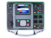
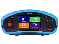
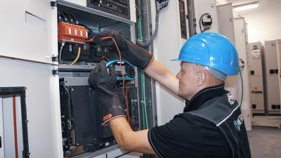
MI 3155 is a multifunctional installation tester that can cover every aspect of the installation from its establishment to years of regular maintenance. Amongst its many features are also three methods for measuring earth resistance. It comes equipped with a number of different probes and test leads for easy testing. The instrument is equipped with 20 m long cables and rods for earth resistance measurements as standard. Optional extensions are available. Software on-board and in the office gives the option to set a maximum resistance limit and gives a pass/fail signal. The test is run automatically once initiated. The result can be saved. Exporting the results to PC allows further processing. The instrument also displays resistances of each measurement electrode for reference. Larger earthing systems can be more easily measured using MI 3144 adapter. It offers higher test current and more measurement options. For more information, please refer to its datasheet and other publications.
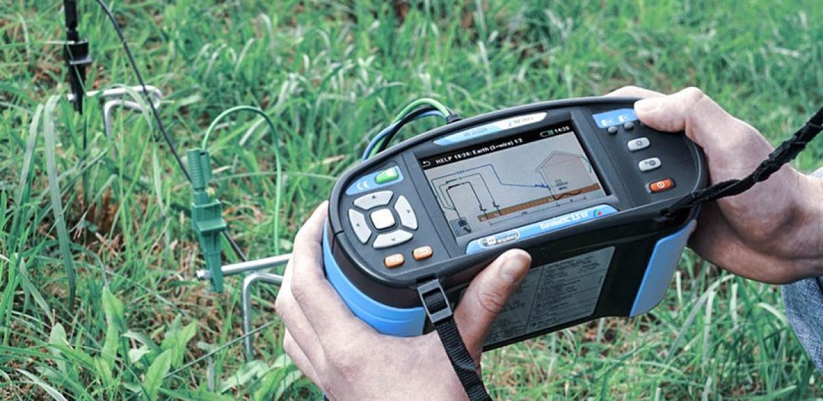
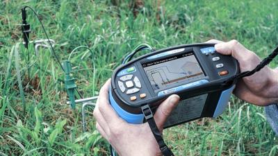
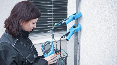
The procedure starts by examining any documentation on the earthing system. The electrical centre of building has to be determined. Rods are set to the required distances and connected with cables to the instrument. Socket designations are H for current electrode, S for voltage electrode and E/ES for the measured earthing probe.
Downloads
| Industrial catalogues | Language | Version | Release | Notes | Type | Size | Download |
|---|---|---|---|---|---|---|---|
| Building Facilities | en | 2023 | 18.12.2023 | 38.72 MB |

|