2-clamps method for measuring lightning and earth protection
Low voltage earthing and lightning protection
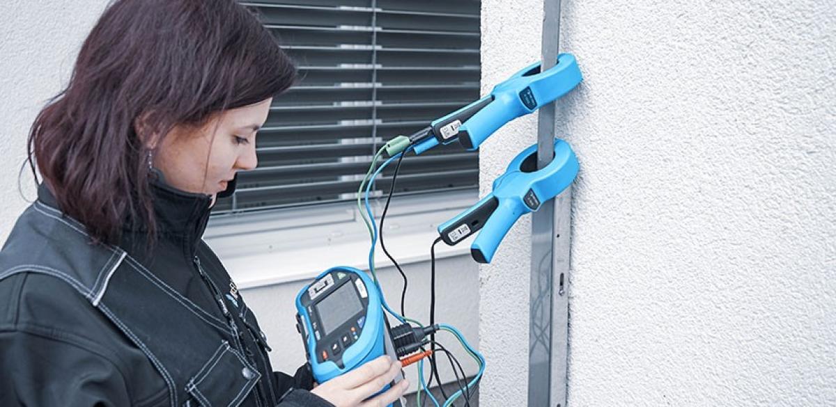
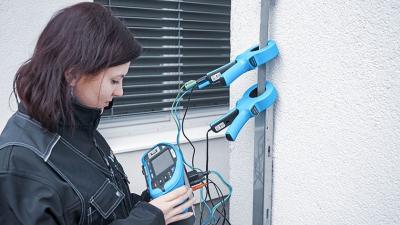
Particularly in urban areas, the classic earthing measurement with rod electrodes isn't possible. There is neither space to put them at a distance from the object to be measured nor access to actual earth to drive in the rod. One has deal with the situation. One alternative is a measurement using two clamps. It is useful for distributed earthing system with a lot of electrodes or for lightning conductors, and quicker and easier to perform than the rod measurements It requires 2 clamps, one a generator for inducing a known voltage to the system and the other for measuring current flowing in the earth electrode under test. The clamps must be as close as possible to the earth electrode, and certainly before any connections to other parts of the earthing system. In a TN system, measurement is performed on incoming PEN/PE bond. No bond needs to be disconnected. Current is injected into the earthing leg as close to the electrode as possible.
A voltage-inducing clamp can be used, or any kind of connector that can be applied to the earth without disconnection. The induced voltage causes current in the whole earthing system. The measurement taken is a loop measurement. In the case of a large system with an internal substation, like a hospital, it goes from the measured point all the way to transformer secondary and back underground through the earthing system. The more parallel earthing rods there are in the system, the closer to resistance of the single rod will the measured value be (example with equal resistances of 10 Ω in Equation 1). It is a quite straight-forward consequence of essentially measuring a single leg in series with a- parallel network in a building.
If the tested electrode has high resistance, that will be immediately obvious. However, if one of the electrodes somewhere in the system is defective, or if there is another error in the loop, the change in measured value might not stand out. It can often only be noticed if there are previous measurements which show a trend. The whole resistance of the system is still low enough, and one failed connection somewhere might not make a difference.
The method lacks a way of proving the result similar to changing the positioning of electrodes in the 3-wire method. The results have to be taken in good faith. It is very important to check for any other low-impedance path that excludes the soil, e.g. antenna in cell tower. Method will not work in that case. Another consideration is the possibility of connection between the earthing electrodes underground. The injected current will then travel by this connection instead of into the ground, and the result
will be falsely low.
Measurements
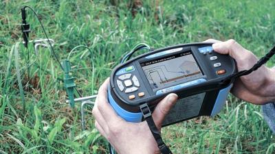
A pair of clamps is part of the standard set for MI 3155. Though their connectors differ: A 1018 has integrated test wire for connection to the instrument, and A 1019 has connectors for standard 3 wire test leads. The only settable parameter is maximum acceptable resistance for pass/fail indication. The measurement is entirely automatic, and it is unimportant which clamp is top or bottom. Use the three-wire test lead and insert it into the test connector on the top of the instrument. Connect the banana connectors one on top of the other and insert into the clamp. Use the current clamp connectors (black and red) to connect the other clamp. Push the button to measure, and save the result as desired.
Downloads
| Industrial catalogues | Language | Version | Release | Notes | Type | Size | Download |
|---|---|---|---|---|---|---|---|
| Building Facilities | en | 2023 | 18.12.2023 | 38.72 MB |

|