Surge protection devices in hospitals
Hospital earthing and lightning protection
Surge protection devices are an important part of lightning protection system. They however can do precious little on their own without a properly designed lightning system behind them.
A surge protection device is designed to redirect current to the ground once the limit voltage is exceeded, and do it very quickly. Some are only conductive when the limit is exceeded, while others switch to a different path, depending on the construction. Reaction times generally stay below 100 ns. They are used at every level of electrical network, from the largest installations to the most sensitive devices, protecting from everything from voltage transients on the network to actual lightning strikes in the close vicinity. They can be grouped by the position in the installation, construction, reaction time, rated voltage, maximum safely diverted current, rise and fall time of the surge they safely divert, and other properties. General guidelines for installation are covered in the standard EN 62305 Lightning protection standard, while the devices usually conform to IEC 61643 Low-voltage surge protection devices.
The surge protection system from top (the supply to the building) to bottom (the assets or appliances) needs to be coordinated so that they open in the right order to an incoming surge. Each level has to be chosen so that it protects equipment behind it, but doesn't age prematurely due to conducting unreasonably often.
Type I protects the installation. A number of these are installed in the main distribution board where the supply enters the building. Exact number, construction type and positioning depend on the grounding system and installation’s power. Ahead of them, sometimes, a thermal fuse is installed, depending on the installation and the SPD manufacturer's instructions.
Type II protects non-sensitive appliances and devices, like large machines. The SPDs are found in the sub-distribution boards between the phase and ground wires.
Type III and IV protect more sensitive devices and are not covered in the scope of this note.
Protection devices have to be installed in a hierarchy of rated voltages, or they might not do their job. A transient of just the right size might burn out too-small a type III device, but fail to trip the type II phase.
Constructions can be a combination of different elements, but the most common are varistors and gas discharge tubes. A varistor is a semiconductor device whose resistance varies with the applied voltage. At low voltage, the resistance is high, but at the rated voltage, it drops off quite sharply. Exact characteristic depends on materials used. Most common is zinc oxide grains, which offer a sharp knee at rated voltage. Varistors have a life expectancy limited by amount of energy they conducted. They may fail catastrophically with a very high power surge or a lightning strike that exceeds their rated current by multiple orders of magnitude. They can remain in conductive state then, or they can open permanently. On the other hand, they can fail with multiple surges over time, and appear undamaged on visual inspection. They generally remain open if they failed over time.
Gas discharge tube is a sealed glass vial, filled with a gas, and with a pair of electrodes inserted. Once the voltage is high enough, the gas ionizes and an arc forms between the electrodes. It is slower than a varistor, by the order of 100 ns. It can conduct higher current per size than any other protection device. The arc can be sustained at voltages lower than the initial one – this is called follow-up current, and it can damage or destroy the device if left unchecked. Similarly to the varistors, they have a finite life expectancy in terms of translated energy over time. They can be designed to short in case of failure, but most commonly they will fail by becoming ineffective. It may need additional protective devices due to its relative slowness and the sustained arc. Their capacitance is exceptionally low, which makes them a good match for higher frequency applications.
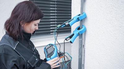
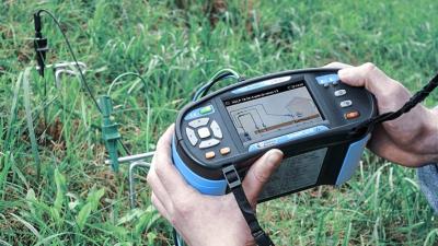
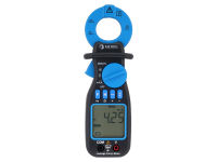
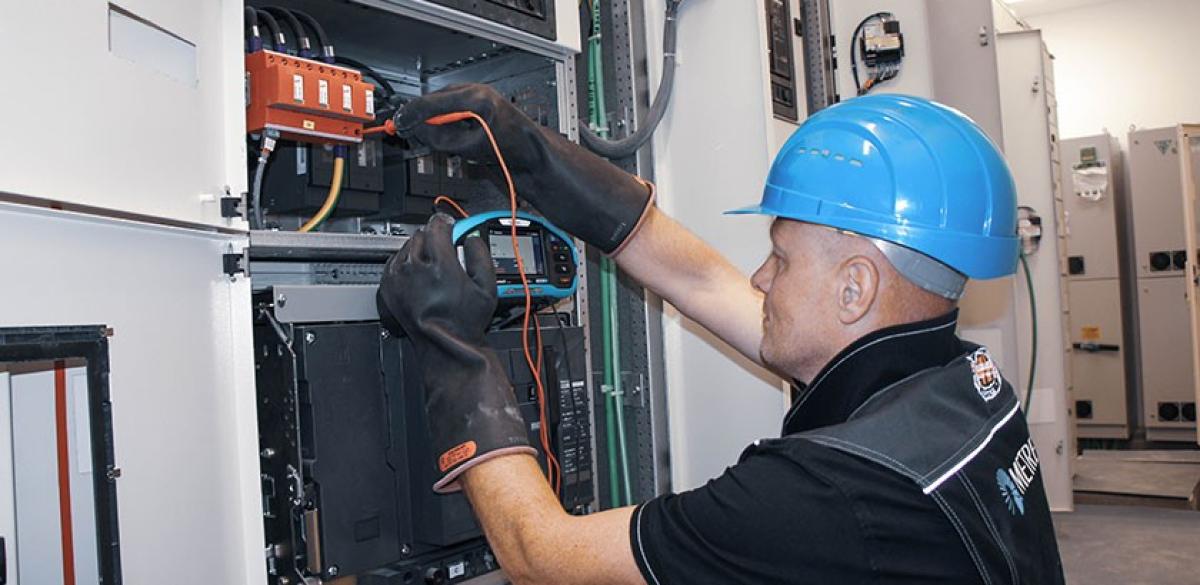
Measurements
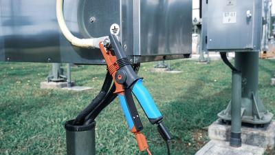
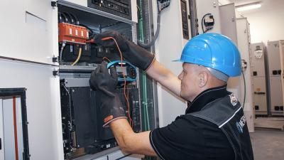
MI 3155 has an automatic test for varistors. Before using it to electrically test them, they have to be thoroughly visually inspected for the following points:
- check the building guidelines,
- check SPD presence,
- check for any obvious signs of failure (breaking, overheating),
- contacts have to be clear and firm (use a thermal camera like MD 9930 if available),
- each units is firmly attached,
- equipotential leads are appropriately sized,
- type and location of installed protection are appropriate to earthing system used,
- check coordination of SPDs,
- check distance from SPDs to their protected location.
The voltage ramps up from 50 V to the set upper limit (1000 V or 2500 V) with slope of 100 V/s (for 1000 V range) or 350 V/s (for 2500 V range). The test ends when the measured current through the device exceeds 1mA or the voltage reaches top of the range. Limit should be set to get a pass/fail evaluation.
Downloads
| Industrial catalogues | Language | Version | Release | Notes | Type | Size | Download |
|---|---|---|---|---|---|---|---|
| Medical Facilities | en | 2023 | 18.12.2023 | 34.02 MB |

|