Impedance of live transformer and fault currents with hot factor
Industrial installations
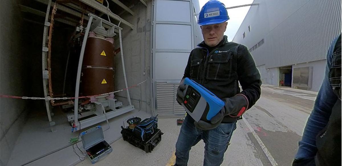
Ability to do predictive maintenace measurements on an online transformer, without disconnecting it, is priceless. The procedure of measuring is comparatively much simpler, although safety procedures may need to be more thorough than with offline equipment. It lowers amount of planning necessary to keep the network working. There may not be need for any extra equipment needed for it.
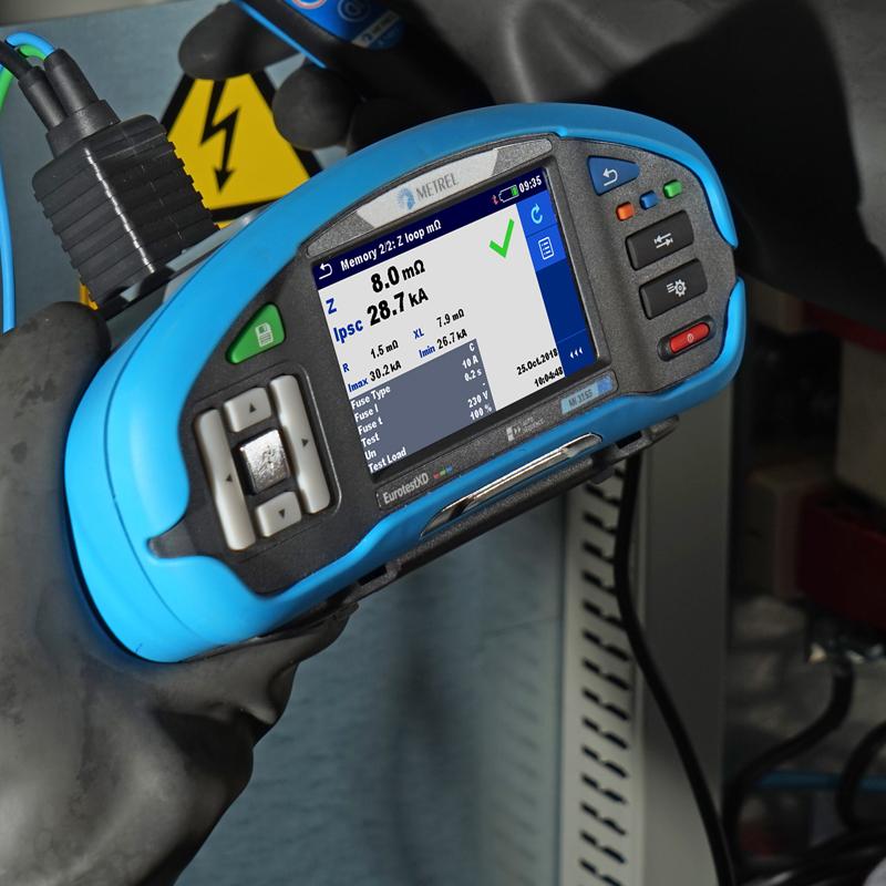
Metrel instruments MI 3144 and MI 3143 can measure impedance of a live transformer, continuity of the contacts, and positions of the tap changer. These combined measurements are then used to calculate the prospective fault current. It is important to consider impedance of the system, not only resistance, as the inductance will have an important influence on the fault current.
Application Notes


Measurements
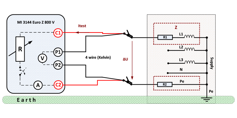
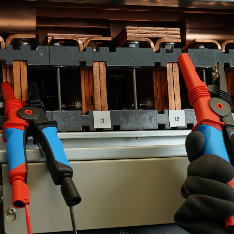
The instrument is connected to the desired contacts of the 3-phase transformer. For line impedance, the high voltage Kelvin clamps are connected so that the instrument is between the phases. For loop impedance, the instrument is connected between one of the phases and the PE connection. Large Kelvin clamps are already insulated, but use of personal protective equipment is necessary. The instrument measures the unloaded voltage on the transformer with high resistance multimeter. Afterwards, it connects a shunt in parallel to the voltmeter and measures both current through it and the loaded voltage. The voltage dip or ΔU is the one needed for impedance calculation.

The measurement lasts half a cycle. Voltage dip this short is very unlikely to cause any kind of trouble in the network.
Results of L to N or L to L need to be compared between phases at the source and at the load. There should be only the calculated differences based on length and cross section of the conductors.
Measurement of line or loop impedance uses the same mathematical principle for live or non-live transformer or installation. In offline case, the no-load voltage is zero and a current is injected so that the result is positive. Measurement is strictly 4-wire and cannot work with other connection types.
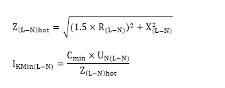
In a 3-phase system the short-circuit current measurements and calculations are done according to standard IEC 60909-0. The standard creates a voltage factor C, the value of which is defined by the desired tolerance in the system. Values are taken from the interval 0.9-1.1. Calculations are done as following:
A system with N conductor
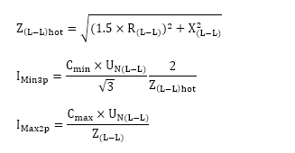
A system without N conductor
Calculated HOT Factor with the measured of Ipsc min and Ipfc min represents unique solutions for predicting the factor of reserve in case of an error on overheated transformers.
More information about the standard and additional calculations can be found in the MI 3144 user manual.
Four-wire type of connection with Kelvin crocodiles for high precision and stable results eliminates problems of bad connectivity and test leads compensation.
Automatic trip out ability evaluation with high accuracy and stability of result even on powerful systems with fuses above 1000 A where classic methods became useless.
Impedance with Resolution of 1mOhm detailed evaluation of transformer’s Isc min, Isc max and Z HOT based on overheating reserve.
Downloads
| Industrial catalogues | Language | Version | Release | Notes | Type | Size | Download |
|---|---|---|---|---|---|---|---|
| Electrical Energetics | en | 2023 | 18.12.2023 | 39.5 MB |

|