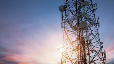
Remote antenna tower earthing resistance
Industrial installations

An antenna tower has a specific problem with measuring its earth resistance: the transmission antenna is always a low-impedance path to earth.
Grounding of an antenna fills three roles: performance in RF transmitting or receiving, safety of personnel and safety from lightning.
In terms of functionality, some antenna designs contain ground connection as necessary integral part of the design. It is often constructed as ground plate that is about a quarter of signal wavelength long. Other types of antennas do not need the earth connection to function, but it can help with their performance to lower some types of disturbances.
Application Notes
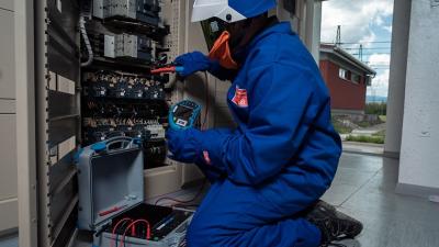

Measurements
Safety of personnel means mainly that the antenna is a large metallic object with a potential to become live. It has to be bonded to the earthing system to minimize dangerous voltage differences and their duration.
Antennas are a lightning bait. The system needs to be well designed and sturdy as lightning strikes are to be expected.
The three systems all depend on low enough resistance towards earth, which is achieved mainly by large contact surface between the earth electrode and ground. Antenna towers are more effective if built on hilltops or other elevated areas, so the ground resistivity is not a big consideration with construction. The electrodes are designed to achieve a low enough resistance.
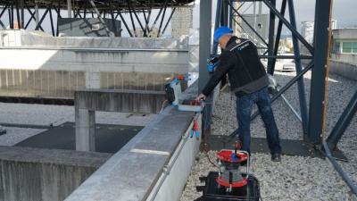
Measuring such a system can be easily achieved by disconnecting the measured electrode from the rest of it and using some form of fall of potential method. Remote areas are well suited to this method. However, disconnection is only possible if the tower is taken offline for the duration of measurement. This is generally undesirable or sometimes even impossible.
It is possible to use the 2-clamp method, but one needs to be careful. The link directly to the ground electrodes can be provided at the distribution panel with this method in mind, but the electrical plan or other documentation should be consulted before measuring there. The length of bonding from the panel to the earth electrode should have a very low resistance and make very small difference in the measurement.
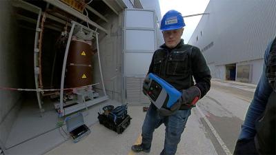
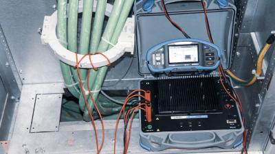
Second important method for antennas is the impulse method. It gauges the impedance of the system in frequency range typical for a lightning strike. The instrument injects a transient pulse with frequency content up to some hundreds of kHz.
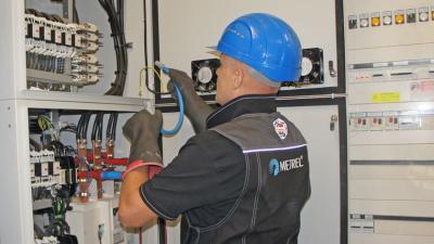
There is a design feature with some of the towers that makes doing the 2-clamp method at the panel inappropriate. The bonding can be done between the earth electrodes in a ring. In this case, measurement at the panel will produce resistance of the ring, not earth resistance. For successful measurement, the clamps have to be applied between the ring and the ground electrodes to force the return path of the loop to go through the ground. The method doesn’t have inbuilt option to check the results like fall of potential method has with moving the electrodes. It is important to keep records from construction time for reference.
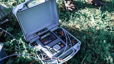
Metrel offers multiple testers that support 2-clamps measurement method. The most basic is MI 3123 with optional clamps. Multifunctional testers MI 3155, MI 3152, MI 3102 all support it. Clamps are already included in some of their standard sets. The method can be also done with MI 3290. It is strongly recommended to transfer the results to MESM and keep track of any changes in the result. The 2-clamp method measures resistance of the whole earthing system and even small changes can mean beginning of a corrosion in the system.
Downloads
| Industrial catalogues | Language | Version | Release | Notes | Type | Size | Download |
|---|---|---|---|---|---|---|---|
| Electrical Energetics | en | 2023 | 18.12.2023 | 39.5 MB |

|