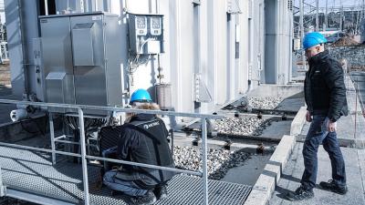
Switchboards and automatic trip-out protection
Low voltage electrical installation safety
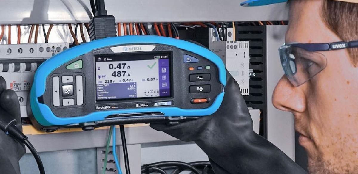
A switchboard or a distribution board is the part of installation where the single main supply in-comer is divided into sub-circuits distribution of power around the building. It incorporates protective measures such as surge protection, circuit breakers and RCDs.
It is the place to conduct a number of tests that would be difficult or impossible in other locations. In particular leakage current measurement and automatic circuit breaking tests are performed here.
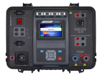
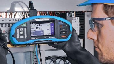
The automatic trip out protection ability test is done to confirm the protection is adequate. It is performed during the initial inspection, periodic predictive maintenance and first response troubleshooting. The use of the MI 3144 is recommended where energetic loads and sources of protection exceed 200 A, like transformers, generators, turbines, contactors, distribution boards and switchyards. It provides high precision methods with high current, temperature management and 4-wire connection.
Methods for partial voltage and current drops enable measurement without disconnecting any wire or removing cable screens. ELR electrical leakage relays are an industrial type of protection in case of high leakage current. They can be properly tested only from switchboard side with fault current injection and trip-out time measurement. Testing relays to proper reaction to faults or leakages, high neutral current, missing phase situations or asymmetry will protect people and livestock as well as electrical loads and supply.
Leakage current measurement is not normally part of periodic inspection, but it is a great troubleshooting tool. Leakage current is both a part of normal operation of installations and devices, usually in the order of mA, and an indication of fault if too high. It is a consequence of imperfect insulation, capacitive coupling, and other parasitic effects. It can be also caused by electro-magnetic disturbances or non-linear filters. This common occurrence can cause a number of problems, most obvious of them being unnecessary RCD tripping and possibility of dangerous touch voltages. RCD tripping can be prevented by using careful design, dividing the circuits between users and switches so that expected maximum leakage for each of the circuits never reaches 20% of RCD rating.
Leakage current manifests as current flowing through the PE conductor, or any unbalance in currents between phase and neutral wires. This gives the key principles of the measuring method. Direct method uses current clamps around the PE cable, but this ignores the potential of parallel earth paths, while differential method clamps phase and neutral cables to measure any unbalance between them. In differential method, direction of each current is important. Ideally, both methods are used and the worse result considered.
Higher than normal leakage can be a symptom of a weakened insulation or a failing device somewhere in the building. After tracing the circuit showing high leakage current, first through the sub-distribution boards, and then by turning the devices on and off sequentially, the source can be located relatively simply.
Leakage current measurement can be an alternative to insulation resistance measurement when looking for failures where high-voltage testing is not possible. That is mainly in presence of sensitive equipment that cannot easily be taken offline e.g. communication or medical devices. Leakage and insulation measurements however are not directly comparable. It depends on the ratio of capacitive and resistive properties of the insulation material. Insulation is measured at high DC voltage and considers only resistive component, while leakage is AC and contains both capacitive and resistive elements.
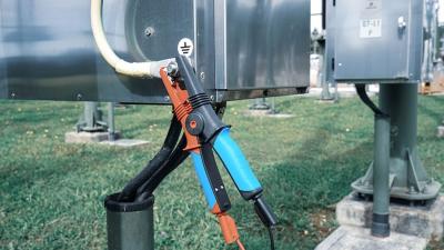
Contact voltages in surroundings of switchboard can be measured during simulated fault to ground. With insulated voltmeter and parallel 1 kΩ resistor connected to simulate body resistance, realistic touch and step voltages can be scaled to faults like phase to ground or even a lightning strike.
Other measurements done in the switchboards are continuity of protective bonding, optionally RCD or ELR tests, voltage properties tests, and power quality logging. See other application notes in this publication for more details.

Measurements
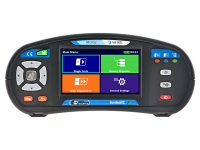
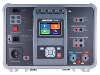
Leakage current is a measurement of a low current in presence of much higher currents in close proximity, which cause significant electromagnetic fields that would result in high errors. Earth leakage clamps should be high quality, with good magnetic shielding and magnetic concentrator in the core that provides a good immunity to external electric fields or capacitive connections, as required by standard IEC/ EN 61557-13. Metrel recommends MD 9272 for work in small enclosures and rapid troubleshooting, MI 3155 with A 1019 for most locations, or MI 3144 for high energy locations that require particularly high precision.
Downloads
| Industrial catalogues | Language | Version | Release | Notes | Type | Size | Download |
|---|---|---|---|---|---|---|---|
| Building Facilities | en | 2023 | 18.12.2023 | 38.72 MB |

|