PAT measurements and management
Portable and fixed appliances
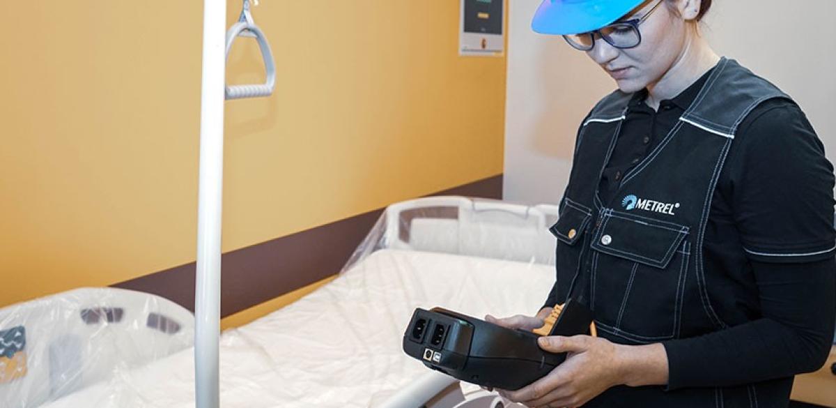
Once passing the visual inspection, portable appliances have to be tested electrically as well. Depending on the local legislation, this can be done by professionals or by laymen. The latter are rather dependant on automation in the instruments that they use, but education is always the preferable way. In essence, there are three electrical tests to be performed on each appliance: continuity of protective earth, insulation resistance and leakage current. Functional test can also include measurement of power parameters. The tests actually performed depend on type of device, its protection class and state of repair.
Protection classes include:
- Class I: connected to PE in the installation with three-pole supply cord, basic insulation (double in case of unearthed accessible parts)
- Class II: not connected to PE, double insulation, two-pole supply wir
- Class III: not connected to mains (battery operated, or through a safety low voltage supply), basic insulation.
Application Notes
Measurements
Earth bond (continuity of protective conductor) test
It determines that PE contacts in the supply cord and grounded metal parts are strong. PE wire prevent dangerous voltages on the accessible parts and conducts any leakage current from the device. It can use currents of 100 mA and higher, depending on the local legislation, device and intention. Most commonly used value is 200 mA. Using higher current can provide better accuracy, and it can also break weakened contacts that would soon fail. Usually, instruments support test currents of 10 A and 25 A. The latter is also prescribed for testing in some special cases in the standards, and for all medical equipment. Test signal is applied between PE pin of the supply cord and accessible earthed part under test. A flexible supply cord has to be folded during test to check contact under every angle. There has to be good contact between the probe and the measured surface – the expected measured values are very low (a couple hundred mΩ) and contact resistance can be considerable.
Insulation
Insulation test determines resistance between live conductors and accessible metal parts of the asset. It is performed with high DC voltage, so it only takes resistance into account, not capacitive or other effects (with exception of brief loading at the start of the test). Resistance depends on the state of the material, which can deteriorate due to a number of external issues. Moisture and pollution are the most common. Weakened insulation can result in dangerous voltage on accessible surfaces, high leakage, RCD trips and overheating. To measure the insulation, the voltage is applied between PE and live pins of the supply cord for Class I protected devices, or between accessible metal part and live pins in Class II protected device. Class III is tested in a similar way to Class II, but the limits are different. If there are no accessible metal parts, the test is not applicable. Voltage used depends on the local legislation and device type. Common values are 250 V or 500 V. After the insulation test, subleakage test is recommended.
Leakage current
There is a number of variants on this test. It is generally performed between accessible metal parts and live while the device is in different working states – the device is turned on. It considers the stray currents at mains voltage and frequency – in AC conditions, which makes it different from an insulation test. It includes capacitive elements and can also be a symptom of a fault in mains circuit or the device. Too high leakage causes high voltages on accessible parts of the device, RCDs tripping, and overheating. Particularly dangerous is a double fault, where protective earth is a not connected. If line and neutral wire positions are not predefined, both options have to be measured and the higher value considered.
PE conductor (direct) leakage
In a class I device, measurement is made on the PE conductor with the device turned on. The floor under the device has to be isolating, or part of the leakage is going to escape through it – this is the main weakness compared to the differential test. If the leakage differs with different working modes of the device, all of them should be checked.
Differential leakage
Both neutral and line wires are passed through the current clamp to measure the difference between them. Current clamp however must be exceptionally well designed to be able to discriminate between the low leakage current from the much higher working current.
Touch leakage
Leakage current measured between line wire and accessible isolated metal parts on both Class I and Class II devices. Device is powered up through the measurement instrument and probe is used on the surface under test. The probe is a human body simulator with resistance of 1 kΩ. Each accessible part of the asset has to be tested separately. MI 3360 M can be used for troubleshooting devices during service.
Medical leakage tests
Medical equipment has to be more thoroughly tested for leakage, since it can be applying voltage directly to patients, who are often in a compromised state. There is a further number of leakage tests to be performed, particularly on the patient-applied parts.
Functional testing
Essence of functional test is to ensure correct operation of the device. In its scope testing the power and leakage combination test can be performed. Usually, current clamps are used for it, and therefore, it is more suited to fixed appliances with higher power. The test can be used to discover problems like stuck motors in danger of overheating, or whether appliances with high nominal currents are causing problems to the installation. Changed power factor can point to problems in supply handing in the appliance.


