Machines and fixed connected loads safety
Machines safety
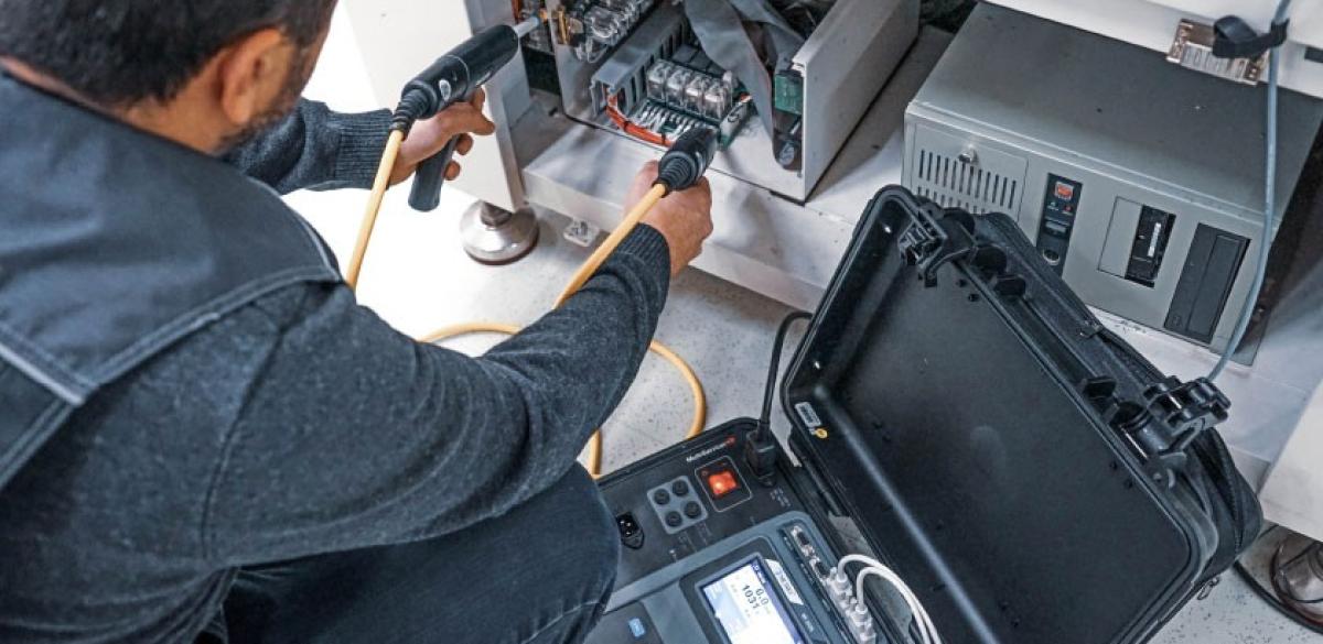
Electrical machines are quite different from appliances. They are comparatively large, their supply can be high-voltage, they are fixed into the installation, their safety depends on state of the installation and they are tested as an assembly. The first test is visual inspection of the machine, any existing technical documentation, and any previous test reports. This determines assembly state of the machine (fully assembled or dismantled), length of supply wires, and its electrical status. Each measurement must be performed on a large number of locations on the machine: motors, control circuits, any sensitive equipment that has to be tested separately, supply circuit, input filters, any built-in protective devices, accessible conductive surfaces, etc. A measurement instrument should be equipped with a memory system and enough probes to allow doing a number of locations at once and change them without losing track.
Application Notes
Measurements
Protection from indirect contact by automatic disconnection
First electrical safety consideration to be tested is protection from indirect contact by automatic disconnection. The exact mechanism and test depend on the grounding system:
- In TN, it is overcurrent devices (covered in standard IEC/EN 60204-1-5),
- In TT, it is a RCDs (standard IEC/EN 60364-6),
- In IT, it is an IMD or RCM (standard IEC/EN 60364-6).
The extent of testing is determined by a decision model or flowchart, based on the information collected. The most extensive variant includes full testing of continuity for all relevant accessible surfaces and cables, and full loop impedance. Test current for continuity of cables is between 200 mA and 10 A, higher currents are preferred, especially for lower resistances. Supplementary protective bonding are grounding connections for any grounded accessible surfaces. Impedance on them has to be low enough to assure contact voltage less than 50 V between any two grounded surfaces.
Fault loop and prospective short-circuit current are measured between L and PE conductors at connection points to the machine’s load, and result compared to relevant protective devices (fuses or breakers). In three-phase machines, all three phases have to be considered. RCDs on a machine are tested for the same results as the installation: trip-out time at nominal current, touch voltage and trip-out current. Supply is on during the measurement. Limits for some of the tested value results are defined by physical properties or technical documentation where available. Acceptable continuity impedance values are calculated from conductor properties: length, cross-section, and material. Disconnection time depends on length of cables and acceptable touch voltage, or can be taken as fixed and used to calculate fault loop impedance. Prospective fault current must consider fuse type and size, nominal voltage, and changes due to temperature. Tables of values are available in standards and supporting literature.
Insulation resistance
As in PAT testing, it is measured between live pins and PE terminal at each eligible machine component. Lower voltage is used on the sensitive components or where built-in protective devices could be operated. On a standard machine and where surge protection can be disabled, the voltage is 500 V and resistance limit is 1 MΩ. On some special parts of the machine, e.g. busbars, conductor bars or slip-ring assemblies, values down to 50 kΩ are allowed. Testing is performed in the same manner as on a portable device – between any insulated part and line wire, and between line and PE wires.
High voltage/withstanding test
Test is usually performed on parts of the machine or installation between power circuit and the protective bonding circuit. Test voltage is twice the nominal voltage of the machine, and tested part should survive 1 s with no insulation breakdown. Any part of the machine not rated to withstand the voltage or that has been previously tested to their standards should be disconnected.
Protection from residual voltage
Residual voltage on live parts is a consequence of material capacitance. The limit for it is 60 V, or the surface has to be discharged to 60 V within 5 s after end of operation. Plugs and similar devices have to be discharged to 60 V in 1 s. If this cannot be achieved, firstly there has to be better IP protection, and secondly extra switching devices and visual warnings shall be applied. Measurement is performed on relevant live parts, most commonly at the supply to the machine, after the device is turned off.
Functional test
Test of machine operating correctly. It can however include other tests that are sometimes also used in troubleshooting: power characteristics, leakage current, or others. Workplace safety Main workplace safety features are connected to safety of devices used daily. Particularly manufacturing workplaces can be hazardous if proper precautions are not observed. Compared to an office or other environment, the production line requires more safety knowledge and action, but also more safety devices and measures.
Hazards and avoiding them
Protection from shock is extended to accidental contacting a live conductor, most common at overhead power wires, but can happen with underground lines or at a substation. Any metallic object can make an accidental contact: a crane, a ladder, metallic construction material, etc. Particularly in construction sites or other incomplete areas, bits of electrical safety measures may be missing. Protective earth or RCD protection may not be in place yet. Such an installation shouldn’t be live. The installation must be tested regularly for safety features like continuity of wires and safety devices working properly. A common hazard is using the equipment in a way not prescribed by the manufacturer. The built in safety may fail to protect the user in such a case. Examples include problems from using obviously damaged equipment, removing its safety features to making extension leads from unsuitable materials. Equipment has to be tested for safety features regularly – frequency of testing depends on working conditions. Non-tested equipment can be considered hazardous
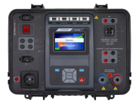
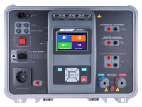
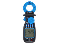
Machines can break in any number of ways. They tend to be complex, with a lot of moving parts and a combination of mechanical and electrical parts. Safety tests can be useful for troubleshooting as well: for example, higher leakage current can be indicative of a problem. If the clamps like A 1472 are used, it can be sometimes determined which part of the machine is causing the higher leakage. Continuity and insulation tests can point to broken wires or failed insulation. A very powerful tool for troubleshooting is a thermal camera like MD 9930. It can identify pressure or friction points that causes parts to wear out prematurely. An overstressed motor’s heat signature is going to be immediately obvious. Regular imaging can help identify devices or components that are more likely to fail as their temperature rises with age. Measuring the temperature remotely can be a powerful maintenance tool. Metrel collection for industrial settings includes MI 3394, MI 3325 and MI 3155. MI 3394 is the most complex Metrel instrument that covers more than 40 safety and functionality measurements. MI 3325 is meant for CE testing of products in the line and less for machinery, but also covers some measurements that MI 3394 doesn't, like DC voltage. MD 3155 is the flagship of installation testers with some machine testing capabilities.
Downloads
| Industrial catalogues | Language | Version | Release | Notes | Type | Size | Download |
|---|---|---|---|---|---|---|---|
| Electrical equipment | en | 2023 | 18.12.2023 | 1.54 MB |

|