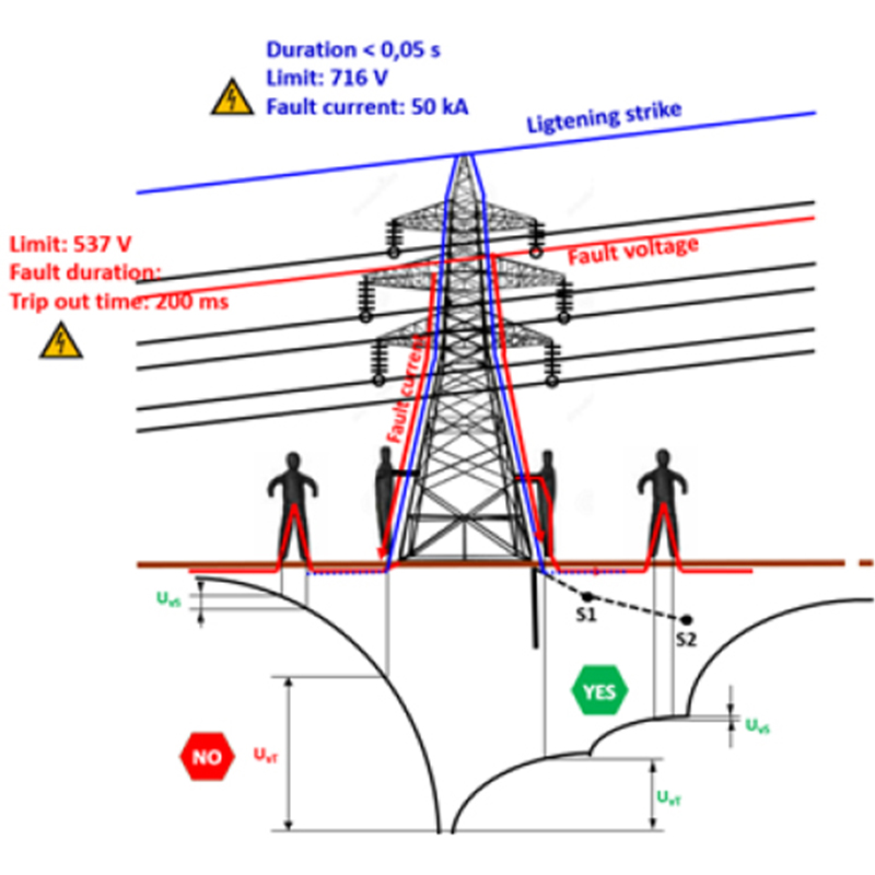
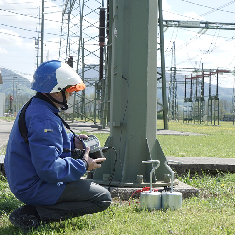
Step and touch voltages with simulated fault
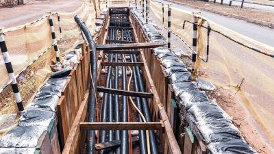
Power distribution
Step, touch and contact voltages in case of a fault are a measure of safety or danger for people during this fault. They assure that the grid meets its design objectives.
Step voltage simulates a voltage between a persons’ legs when walking and between ground and a touchable conductive surface that may become live. It is particularly relevant outdoors when close to a grounding electrode of a high voltage system (power generation station, substation, distribution pylons/towers), or any grounded metal-work: meshes, fences, pipes, bridges, rails, etc. Fault voltage can travel very far through conductive or inductive connections.
Application Notes
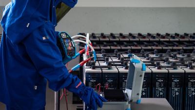
Measurements
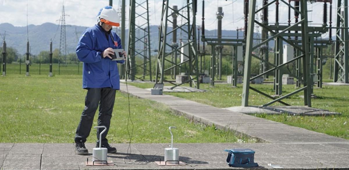
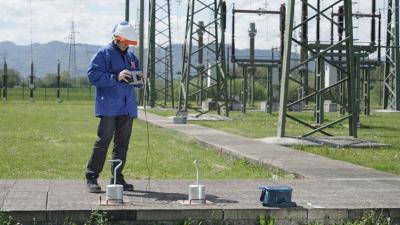
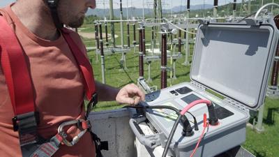
It is measured between points 1m apart on the ground during a fault. The fault is simulated with injected current into the grounding system and mathematically scaling it to the prospective magnitude. A person is simulated with a pair of weighted electrodes: 25 kg conductive weights or a pair of plates that can be stepped on (with insulating shoes). A voltmeter used must have a low input impedance that is similar to resistance of a human body, about 1 kΩ. A 1 kΩ resistance in parallel to a high-resistance voltmeter can also be used, like the Metrel A 1597 Human body resistance probe.
Contact voltage is a variation to touch voltage that avoids the human resistance probe and uses a voltmeter with high input impedance. It gives different information, but can be used in a similar way.
Touch voltage can be relevant indoors as well, but usually a different method is used for measuring it there.
MEASUREMENTS
A fault-simulation current is injected into the ground and the voltage between the ‘leg’ electrodes is measured. Two electrodes are necessary at a distance from each other to complete the circuit. The distance is recommended to be at least five times the diagonal of the measured object.
Contact voltage is measured between a point on the ground 1 m away from the grounded conductive object and a point on the object. The same weights or electrodes as for step voltage measurement are used to simulate a person touching the object. The current is injected into a surface on the object and returned by a distant electrode. Again, the distance is at least five times the length of diagonal.
In both cases, the instrument will calculate the value of voltage in case of a much larger fault, like a lightning strike. This is called scaling.
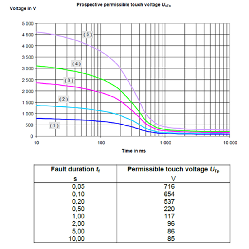
The tolerated values depend on duration of a fault. In case of a lightning strike, the voltage can reach quite high values as long as it passes too quickly to do damage. In case of a phase to ground fault that lasts until fixed, the value cannot exceed 50 V. See the table for more information.
Both methods are described in the standard IEEE-81 and are considered part of a thorough analysis of an earthing system and equipotential bonding. Other standards like IEC 62305 include them too.
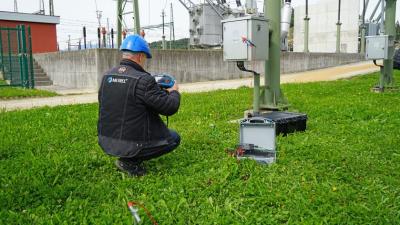
Metrel offers a number of instruments that support measuring step, touch and contact voltage. MI 3290 Earth analyser is compact and powerful, but the larger MI 3295 Step Contact meter offers more power (up to 350 W) for noisy or otherwise difficult environments. Weights and voltmeter with 1 kΩ internal resistance are part of the standard set. The memory holds up to 1000 results in a 3-level memory structure that can be transferred to PC for further consideration.
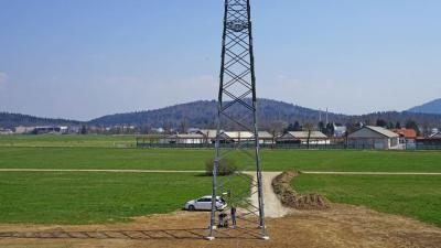
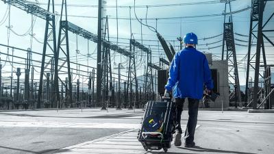
MI 3290 is particularly useful in isolated locations like distribution pylons or antenna towers. Its compact shape and battery power allows for a lower and slower current injection compared to MI 3144 or MI 3295. Since the isolated locations are low on noise, this is sufficient.
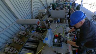
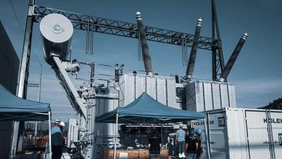
Periodic measurements of grounding system integrity in the 110 kV distribution system between Ivančna Gorica and Trebnje in Slovenia were done using MI 3295S generating station and two synchronised MI 3295M voltmeters. Previously done measurement and design documentation for the measured area were available. The voltage funnel was measured using step and contact voltages at typical employee standing locations. Both the flat and the weighted probes were used. The instrument automatically scales the measured values to the chosen size of the lightning strike 60 kA. The value was chosen as worst-case lightning strike, since the symmetrical connections to nearby pylons causes the strike to spread over the area and lower any local voltage. Similarly, the lightning protection wires can carry the current to next pylons, further protecting the immediate area of the strike.
The lightning strike is a very brief event. Using the values about 0.1s after the current injection is a good reasonable approximation.
Downloads
| Industrial catalogues | Language | Version | Release | Notes | Type | Size | Download |
|---|---|---|---|---|---|---|---|
| Electrical Energetics | en | 2023 | 18.12.2023 | 39.5 MB |

|