Transformers ratio, winding resistances, tab changer and connections
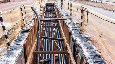
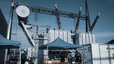
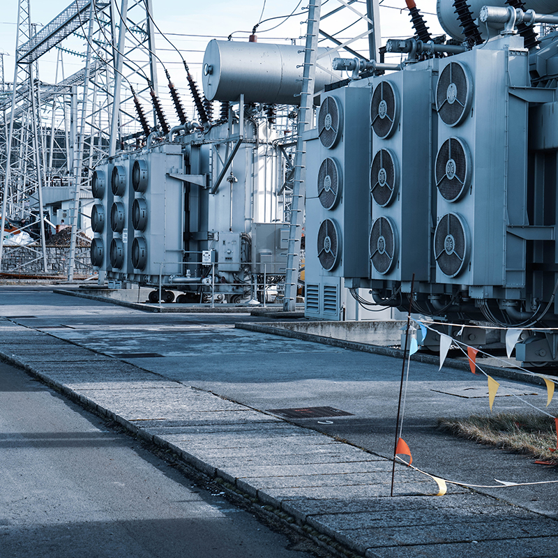
Power distribution
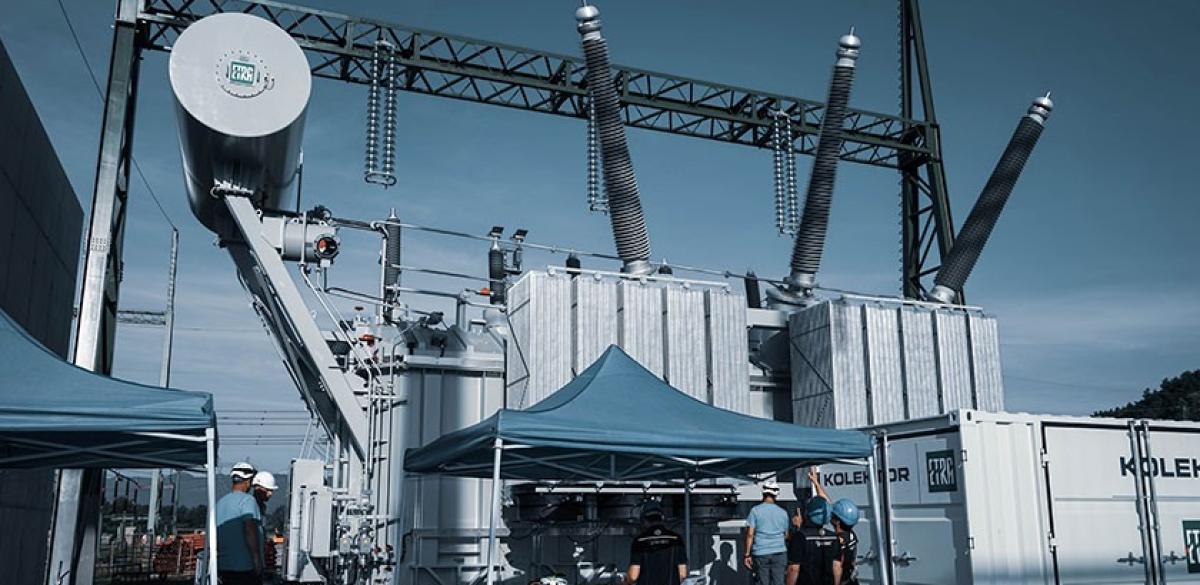
Damage in transformers can be caused by poor design, poor maintenance, overheating, or other. It can show as shorted turns, changes in turn ratio, loose connections and weakened contacts on tap changers. The measurements look at absolute resistance value of each winding, differences between windings in a transformer and possible open connections.
Transformer ratio means ratio of voltages and also number of turns on each side of it. This is also the measuring method: inducing AC voltage at a bit higher than nominal frequency in primary side and measuring it on the secondary. It should be within 0,5% the nameplate value. Reasons for changes in ratio include failures in insulation between turns, turns breaking, and similar occurrences. Main issue that causes the breaks is overheating due to cooling failure or overcurrent. Higher frequency is used to avoid disruptions at the nominal frequency.
Taps are contacts to the winding at different positions and therefore at different ratios. Tap changer is a mechanical device that moves connections to them. Tap evaluation means testing each tap position for continuity. The contact should be firm, safe and have a low resistance to prevent any chance of overheating. An ‘on load’ tap changer can change ratio while energised, while ‘off load’ needs to be disconnected and demagnetised before changing.
Application Notes
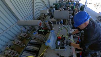


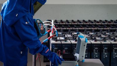
Measurements
The measurement of winding resistance is simple in the essence: apply a DC current to the windings and measure the voltage to calculate the resistance. The core must saturate and the system must be in balance for a sensible result to emerge. Inductance of the windings causes a transitional effect that can last a couple of minutes for very large transformers. Test results cannot be taken at face value. At the very least, they are compared to the adjacent winding in 3-phase transformer at the same tap that is assumed to have the same temperature. They have to keep within 1% of each other. It is also possible to use the previously taken saved measurements if the temperature of the windings during measurement is known for temperature correction of the results. Results can only be compared at the same temperature. Most large transformers have a temperature gauge built-in, or oil temperature can be assumed to be about the same as windings’.
To be thorough each tap position should be tested, but during routine maintenance, usually only the currently designated is. This is particularly true if transformer is equipped with ‘off-load’ tap changer. The transformer must then be discharged before changing tap and the measurement takes a very long time. With ‘on-load’ tap changer, the measurement can be left running while changing taps. This tests functionality of the tap changer as well.
After measurement demagnetize the transformer. It ensures smooth restart to its job. Use one of the windings and a demagnetizing current form.
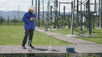
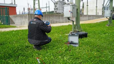
Connection of the instrument is generally at each end of the winding under test with Kelvin clamps. Primary and secondary can be tested at the same time if two measuring instruments are available. Three-phase transformers with dual windings are best tested with an extra voltmeter, while there can be only one current source. Care with connections can lower time to core saturation.
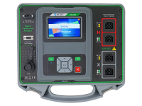
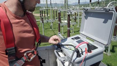
Metrel MI 3280 Digital transformer analyser is a specialised instrument for testing single and three phase transformers. The new UI offers easy work with references always in reach. Windings resistance can also be measured with the MicroOhm line of tester by Metrel, like MI 3252. With its high current even the largest transformers can be tested safety. It however doesn’t include the smart features and ease of work of MI 3280.
MI 3144 supports a test of live transformer’s windings with high current. This method also tests the automatic trip-out ability of the installation.